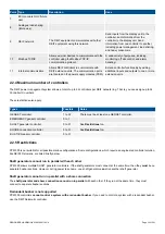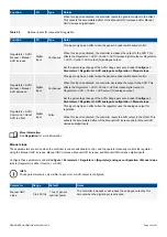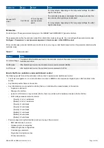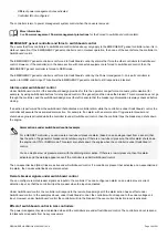
Configurable hardware
After you assign a function to an input or output, you can assign parameters to that function. Each controller type has a default
configuration.
Most of the controller inputs and outputs can be assigned any function. Functions are
not
restricted to specific hardware modules.
For example, governor and AVR control functions can use any inputs and outputs, and do
not
have to use the inputs and outputs on
the Governor and AVR module (GAM3.1).
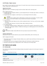
Variety of input and output types
The DEIF controllers often allow the same function to use a number of alternative types of inputs and/or outputs. This makes the
controllers very versatile and compatible with a wide range of equipment and systems.
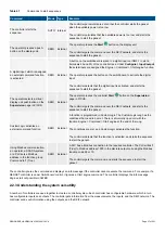
For example, a generator breaker close can be initiated by the power management system for a GENSET controller in AUTO mode.
Alternatively, if the GENSET controller is in SEMI mode, an operator using the display unit, PICUS, a digital input, CustomLogic, or
an external system using a Modbus command can initiate the generator breaker close.
Similarly, the generator excitation can be controlled using an analogue output, or digital outputs.
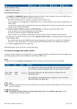
Finally, the DEIF network allows information from all the controllers to be used by any of the controllers. For example, for power
management, the analogue and digital inputs and outputs for a heavy consumer can be connected to a SHAFT generator controller.
The SHAFT generator controller shares the power management information with the rest of the system, even if the shaft generator
itself is not connected while the heavy consumer is active.
INFO
Each controller's display unit only displays the operating information for that controller. However, the controller processor
also has access to operating information from the rest of the system.
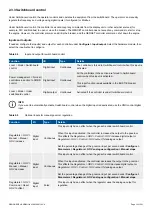
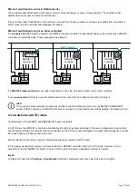
Information flow
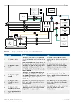
The following drawing gives an overview of the ways that information can flow between a GENSET controller and the genset it
controls. The drawing also shows the information flow to the display unit, another controller, a PLC, and the switchboard.
DESIGNER'S HANDBOOK 4189340911K UK
Page 28 of 521


