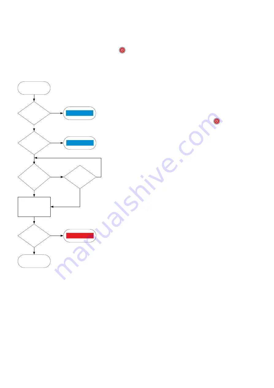
8.4.2 Engine stop flowchart
The following flowchart shows how the controller normally stops a genset. An engine shutdown is described later.
This flowchart does not apply to switchboard control. When the controller is under switchboard control, it will not stop the genset. If,
for example, the operator presses the push-button
Stop
on the display unit, the controller ignores this command, and the
controller display unit shows an info message.
Table 8.17
Engine stop flowchart
Genset stop
command
GB open
No
Yes
Stop engine
Running
detection
OFF
No
Yes
Genset
stopped
Command
and mode
match
No
Yes
Stop
pressed
again
Yes
No
Cooldown
timer
expired
No
Yes
Alarm
Info message
Info message
1.
Command and mode match:
The controller checks that the command
source and the controller mode match:
•
In AUTO mode, the power management system must send the command
to stop the genset. The controller ignores all other external commands.
•
In SEMI mode, the command to stop the genset can come from the
following:
◦
The operator can press the push-button
Stop
on the display unit.
◦
The operator can use PICUS to send an engine stop command.
◦
The command can come from an external source, like a PLC.
2.
GB open:
The controller checks whether the genset breaker is open. If the
genset breaker is not open, the controller cancels the stop sequence and the
display unit shows an info message.
3.
Cooldown timer expired:
The genset runs without load for the cooldown
time. The controller checks whether the cooldown timer has expired or the
stop button was pressed again.
•
If the cooldown timer has not expired, but the engine stop button is
pressed again, the controller stops the cooldown.
4.
Stop engine:
To stop the engine:
•
Stop coil system: The controller activates the
Stop coil
output.
•
Run coil system: The controller deactivates the
Run coil
output.
5.
Running detection OFF:
The controller checks whether the engine has
stopped.
•
If
Running detection
is ON, the controller activates an alarm.
•
If
Running detection
is OFF, the engine has stopped and the stop
sequence has been completed successfully.
8.4.3 Engine stop sequence
These sequence diagrams show the engine stop sequence.
DESIGNER'S HANDBOOK 4189340911K UK
Page 297 of 521


