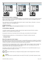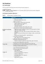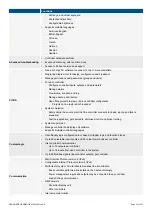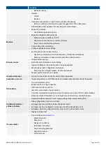
2.3.3 Switchboard control
Under
Switchboard control
, the operator controls and operates the equipment from the switchboard. The operator can manually
regulate the frequency and voltage using digital inputs (if configured) or Modbus.
Under
Switchboard control
, the controller does not accept any commands from the display unit or other external sources (for
example, PLC and Modbus) to open or close the breaker. The GENSET controller does not accept any commands to start or stop
the engine. However, the controller alarms can still trip the breaker, and the GENSET controller alarms can shut down the engine.
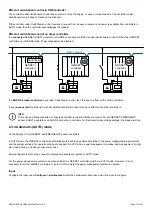
Inputs and outputs
If needed, configure the input(s) and output for each controller under
Configure > Input/output
. Select the hardware module, then
select the input/output to configure.
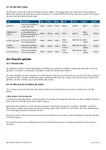
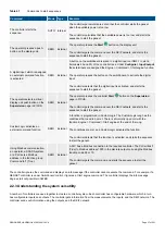
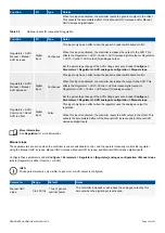
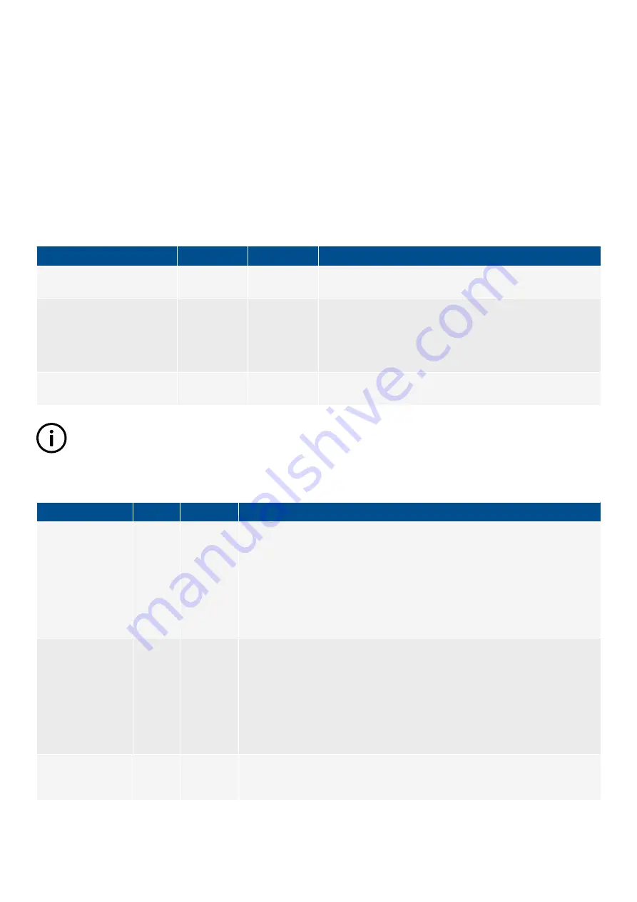
Table 2.4
Input and output for switchboard control
Function
I/O
Type
Details
Local > Mode > Switchboard
control
Digital input
Continuous
The controller is forced to
Switchboard control
when this input is
activated.
Power management > Force all
controllers in section to SWBD
control
Digital input
Continuous
All the controllers in the section are forced to
Switchboard
control
when this input is activated.
This input function is
not
available in the BUS TIE breaker
controller.
Local > Mode > Under
switchboard control
Digital output
Continuous
Activated if the controller is under
Switchboard control
.
INFO
If you want to automatically activate
Switchboard control
when the digital input is deactivated, use the
PMS control
digital
input.
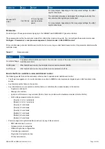
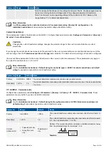
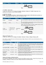
Table 2.5
Optional inputs for manual governor regulation
Function
I/O
Type
Details
Regulators > GOV >
Manual > Manual
GOV increase
Digital
input
Continuous
This input only has an effect when the genset is under switchboard control.
When this input is activated, the controller increases the output to the governor.
This affects the
Regulators > GOV > Control > GOV increase
digital output or
Regulators > GOV > Control > GOV output [%]
analogue output.
Set the percentage change of the governor input per second under
Configure >
Parameters > Regulators > GOV analogue configuration > Manual slope
.
Regulators > GOV >
Manual > Manual
GOV decrease
Digital
input
Continuous
This input only has an effect when the genset is under switchboard control.
When this input is activated, the controller decreases the output to the governor.
This affects the
Regulators > GOV > Control > GOV decrease
digital output or
Regulators > GOV > Control > GOV output [%]
analogue output.
Set the percentage change of the governor input per second under
Configure >
Parameters > Regulators > GOV analogue configuration > Manual slope
.
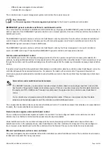
Regulators > GOV >
Command > Reset
GOV to offset
Digital
input
Pulse
This input only has an effect when the regulator uses the analogue output for
regulation.
DESIGNER'S HANDBOOK 4189340911K UK
Page 33 of 521


