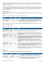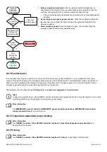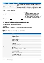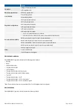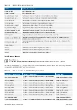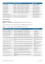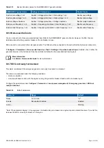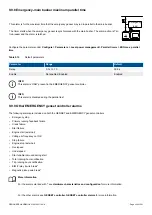
The emergency genset controller configuration affects the response of the system after a blackout. This response also depends on
whether the controller controls the emergency genset governor.
9.7.2 Emergency genset as part of the system
When the EMERGENCY genset controller is part of the power management system, it shares information with the other controllers
over the DEIF network.
As part of the system, the emergency genset can operate in parallel to the busbar. This can be for short periods (load take-over), or
for extended periods (harbour operation).
More information
See
Other EMERGENCY genset controller functions
,
Harbour operation
in this chapter for more information.
Figure 9.2
An example of an emergency genset as part of a system
Genset
Shaft generator
Emergency genset
G
G
G
Emergency
load
BUS TIE
breaker
controller
SHAFT
generator
controller
EMERGENCY
genset
controller
DEIF network
GENSET
controller
Genset
G
GENSET
controller
DEIF network
9.7.3 Stand-alone emergency genset
For some applications, the emergency genset must be a stand-alone genset. For a stand-alone genset, the EMERGENCY genset
controller is not connected to the DEIF network.
Single-line diagram
For a stand-alone emergency genset, the emergency genset must be the only component shown in the EMERGENCY genset
controller single-line diagram. The stand-alone emergency genset must not be included in the rest of the system's single-line
diagram.
INFO
For a stand-alone emergency genset application, do not include the EMERGENCY genset controller in the
Broadcast
when
broadcasting the single-line diagram from another controller. Similarly, do not
Broadcast
the single-line diagram to other
controllers for a stand-alone emergency genset application.
DESIGNER'S HANDBOOK 4189340911K UK
Page 337 of 521


