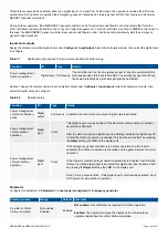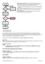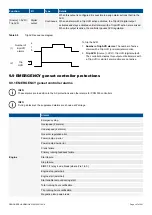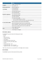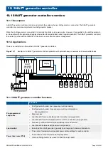
Figure 9.3
Example of a stand-alone emergency genset application
Genset
Shaft generator
Emergency genset
G
G
G
Emergency
load
BUS TIE
breaker
controller
SHAFT
generator
controller
EMERGENCY
genset
controller
DEIF network
GENSET
controller
Genset
G
GENSET
controller
DEIF network
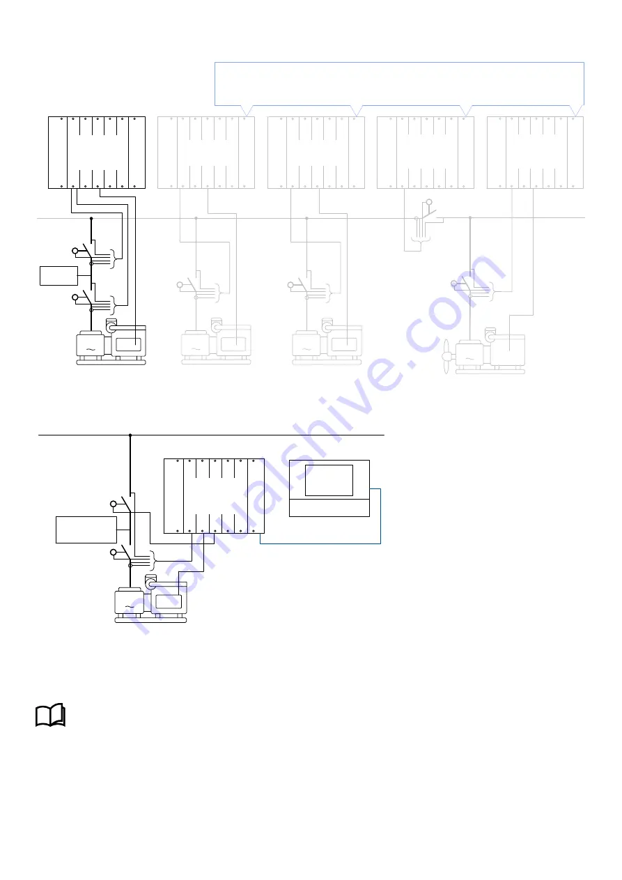
Figure 9.4
Stand-alone emergency genset
Emergency
load
Emergency genset
G
EMERGENCY
genset
controller
Display
Tie breaker
Genset breaker
Input
Optional: You can configure the
Main busbar is OK
digital input.
More information
See
EMERGENCY genset controller
,
Emergency genset configurations
,
Main busbar is OK
for more information.
AUTO mode
The controller uses its AC measurements (from the ACM) and, if configured, the
Main busbar is OK
digital input, to determine
whether there is power on the main busbar. If there is power on the main busbar, in AUTO mode the controller ensures that the tie
breaker is closed and the generator breaker is open.
DESIGNER'S HANDBOOK 4189340911K UK
Page 338 of 521


