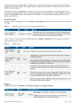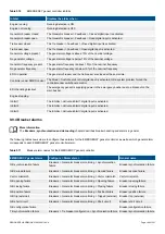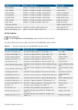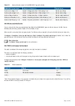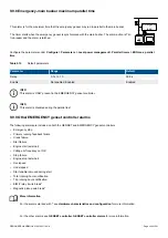
9.8.6 Temperature-dependent start/stop
More information
See
GENSET controller
,
Other GENSET controller functions
,
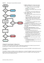
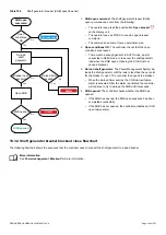
Temperature-dependent start/stop
for a description of
this function.
9.8.7 Engine states as digital outputs
You can configure a digital output with a function for an engine state. The controller activates the digital output if the engine state is
present. These can be useful for troubleshooting.
More information
See
GENSET controller
,
Other GENSET controller functions
,
Engine states as digital outputs
for more information.
9.8.8 Engine operating values as analogue outputs
You can configure an analogue output with a function for an engine operating value. The controller receives this value from an
engine measurement. The controller then adjusts the analogue output to reflect the engine operating value.
More information
See
GENSET controller
,
Other GENSET controller functions
,
Engine operating values as analogue outputs
for more
information.
9.8.9 Counters
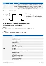
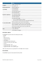
The EMERGENCY genset controller includes the same counters as the GENSET controller.
More information
See
GENSET controller
,
Other GENSET controller functions
,
Counters
for more information.
In addition, the EMERGENCY genset controller includes counters for tie breaker operations and trips.
9.8.10 EMERGENCY genset controller without regulation
In some cases it might not be possible to regulate the emergency genset speed using the controller. For these situations you can set
up your controller to synchronise and de-load your generator breaker and/or tie breaker over the network.
To send synchronisation information over the network, the analogue or relay governor inputs must not be configured. To synchronise
with the busbar, the controller sends the synchronisation information over the network to the available genset controllers. The
GENSET controllers synchronise over the breaker and the EMERGENCY genset controller closes the breaker once the busbars are
synchronised.
To de-load and open the breaker, the EMERGENCY genset controller sends a de-load request to the available GENSET controllers.
The GENSET controllers de-load the breaker, and the EMERGENCY genset controller opens the breaker.
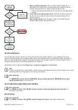
9.8.11 Trip AVR
The
Trip AVR
output ensures that excitation is stopped when an alarm activates with a
Trip AVR
alarm action. In cases where there
is high voltage present, stopping the excitation reduce the time required to stop an engine in case of an emergency.
The
Trip AVR
output and alarm action does not initiate a breaker trip. To trip the breaker and the AVR, digital outputs for both actions
must be configured and the correct alarm action must selected. For example, the
Trip b AVR
alarm action.
Inputs and outputs
Assign the
Trip AVR
output under
Configure > Input/output
. Select the hardware module, then select the output to configure.
DESIGNER'S HANDBOOK 4189340911K UK
Page 346 of 521


