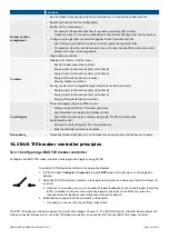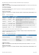
How it works
In the description below, the connecting equipment can either be a genset that connects to a busbar powered by one or more shore
connections, or a shore connection that connects to a busbar powered by one or more gensets. The connecting equipment
controller controls
Breaker 1
, while the connected equipment controller controls
Breaker 2
.
When the
Overlap
function is enabled on a shore connection controller, the controller checks whether the connecting equipment can
take over the load from the busbar. If the connecting equipment can take over the load from the busbar, the controller closes the
breaker (
Breaker 1
). The breaker(s) that would normally de-load and open after the connecting equipment takes over the load from
the busbar (
Breaker 2
), opens immediately without de-loading the breaker. It is only possible for a controller to open
Breaker 2
, if the
controller is under PMS control.
If a system has multiple shore connections and only one has the
Overlap
function enabled, then all the connected shore connections
open without de-loading when the sensitive shore connection opens. For example, shore connection 1 (SC1) and shore connection
2 (SC2) are connected to the same busbar. SC1 has the
Overlap
function enabled. If there is a request to open the breaker of either
SC1 or SC2, then both breakers open without de-loading when the genset connects to the busbar.
If a controller is under switchboard control, the breaker is not opened when a sensitive shore connection connects to the busbar.
However, after the timer for the
DG-SC max. parallel time
protection expires, the controller trips the generator breakers that are
closed to protect the gensets.
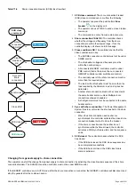
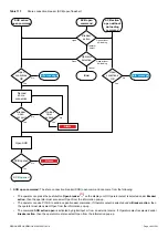
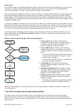
Sensitive shore connection breaker close and open flowchart
[Breaker 1]
close command
Open
conditions
OK
No
Yes
Close
[Breaker 1]
[Breaker 2]
opened
Overlap
enabled
No
Yes
Info message
[Breaker 1]
standard close
sequence
Immediately
open
[Breaker 2]
1.
Overlap enabled:
The controller of the connecting
equipment checks whether
Overlap
is enabled on the shore
connection controller. If
Overlap
is not enabled, then a
standard breaker close sequence is followed.
2.
Open conditions OK:
The controller of the connecting
equipment checks if the open conditions for the connected
equipment (
Breaker 2
) are OK. The following conditions must
be met:
•
The section must have at least one other source of power
ready to connect to the busbar (for example, a running
genset or shore connection).
•
The connecting equipment must not be overloaded when
it takes over the load on the busbar.
3.
Close [Breaker 1]:
The controller of the connecting
equipment activates the
Breakers > [Breaker] > Control >
[*B] Close
output.
4.
Immediately open [Breaker 2]:
If the breaker has closed,
then each controller of all the connected equipment that is
under PMS control immediately activates the
Breakers >
[Breaker] > Control > [*B] Open
output.
5.
[Breaker 2] opened:
Each controller of all the connected
equipment that is under PMS control checks whether the
breakers have opened.
•
If the breaker has opened, the sensitive shore connection
breaker sequence has been completed successfully.
Note: In the flowchart
[Breaker 1]
refers to the breaker of the connecting equipment, and
[Breaker 2]
refers to the breaker of the
connected equipment.
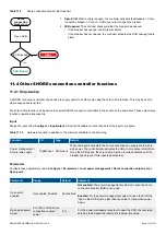
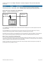
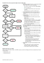
11.4.6 Shore connection load transfer without parallel
If two power sources cannot be synchronised, then you cannot transfer the load directly from the one to the other without
interrupting the supply. For example, you cannot transfer the load directly from a shore connection to an unsynchronised shore
connection, or from a shore connection to a shaft generator, or to a synchronised shore connection if the parameters only allow one
shore connection.
DESIGNER'S HANDBOOK 4189340911K UK
Page 393 of 521


