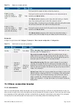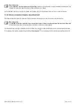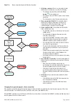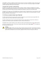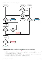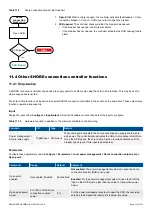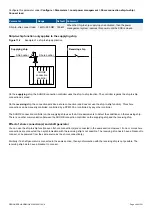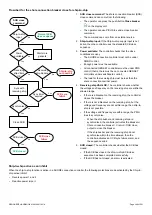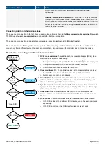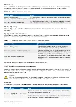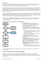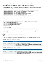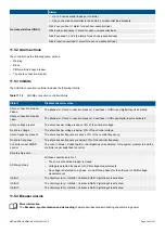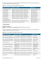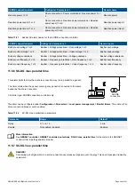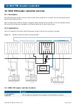
However, the power management system includes a pre-programmed sequence to automatically transfer load. It does this by using
gensets in AUTO mode to supply the load during the transition (if they can supply the load). The sequence starts when the operator
presses
Close
on the non-connected SHAFT generator or SHORE connection controller display unit.
For a load transfer using gensets from a shore connection to an unsynchronised shore connection, the steps of the sequence are:
1. The operator presses
Close
on the second SHORE connection controller display unit.
2. The power management system starts and connects enough gensets to take the load from the first shore connection.
3. The power management system regulates the gensets so that they de-load the first shore connection.
4. The power management system opens the first shore connection breaker.
5. The power management system synchronises the gensets to the second shore connection.
6. The power management system closes the second shore connection breaker.
7. The power management system regulates the gensets to transfer the load to the shore connection.
8. The power management system disconnects and stops the gensets.
11.4.7 Counters
You can view, edit and reset all the counters on the display unit under
Configure > Counters
. The counters include:
•
Shore connection breaker operations and trips
•
Active and reactive energy export (to the shore connection)
•
Active and reactive energy import (to the ship busbar)
•
External breaker operations
Energy counter outputs
For each energy counter, you can configure a digital output to send a pulse every time a certain amount of energy is transferred.
Configure the digital outputs under
Input/output > Digital output > Functions > Shore connection > Energy counters >
[Counter pulse]
.
INFO
You must configure the digital output function to see the parameters.
Configure the energy transfer required for a pulse under
Parameters > Shore connection > Energy counters > [Counter]
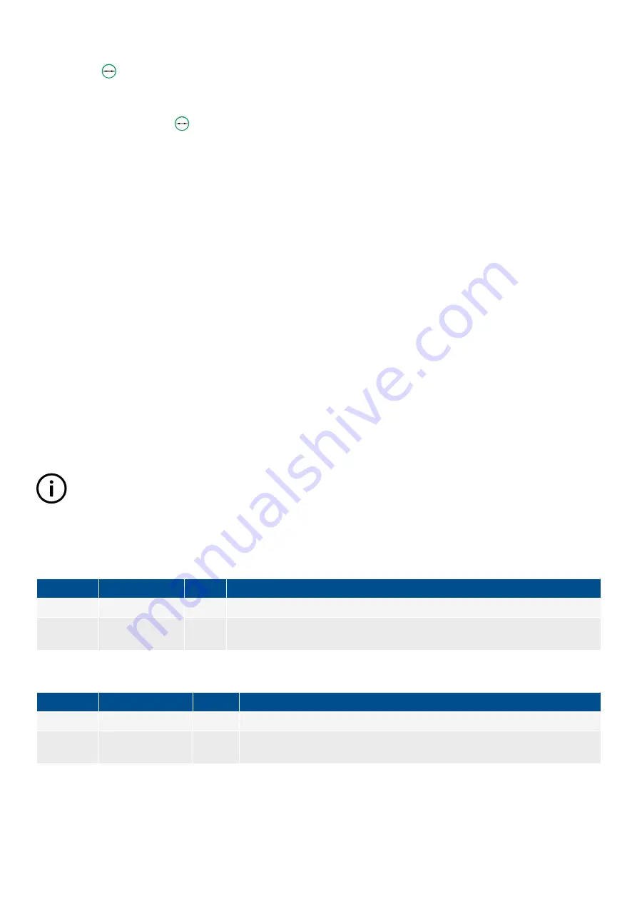
Table 11.13
Active energy export counter parameters
Parameter
Range
Default Comment
Pulse every 1 kWh to 10 MWh 10 kWh The value when a digital output sends a pulse.
Pulse length 0.1 s to 1 h
1 s
The length of the pulse that is sent. This value should be long enough so the pulse
can be registered by the external counter.
Table 11.14
Reactive energy export counter parameters
Parameter
Range
Default
Comment
Pulse every 1 kvarh to 10 Mvarh 10 kvarh The value when a digital output sends a pulse.
Pulse length 0.1 s to 1 h
1 s
The length of the pulse that is sent. This value should be long enough so the pulse
can be registered by the external counter.
DESIGNER'S HANDBOOK 4189340911K UK
Page 394 of 521

