Alarms
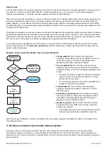
Non-essential load (NEL)
•
Up to 3 non-essential loads per controller
•
Can connect each controller to the same 3 non-essential load breakers
NEL # over-current (1 alarm for each non-essential load)
NEL # under-frequency (1 alarm for each non-essential load)
NEL # overload 1 and 2 (2 alarms for each non-essential load)
NEL # reactive overload (1 alarm for each non-essential load)
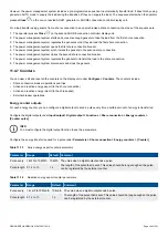
11.5.2 Alarm actions
The controller has the following alarm actions:
•
Warning
•
Block
•
PMS-controlled open breaker
•
Trip shore connection breaker
11.5.3 Inhibits
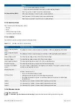
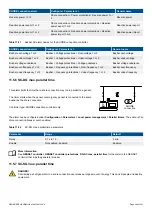
The SHORE connection controller includes the following inhibits:
Table 11.18
SHORE connection controller inhibits
Inhibit
Disables the alarm when ...
Shore connection breaker
closed
The
Breakers > Shore connection breaker > Feedback > SCB closed
digital input is activated.
Shore connection breaker
open
The
Breakers > Shore connection breaker > Feedback > SCB open
digital input is activated.
Shore voltage present
The shore busbar voltage is above 10% of the nominal voltage.
No shore voltage
The shore busbar voltage is below 10% of the nominal voltage.
Shore frequency present
The shore busbar frequency is above 10% of the nominal frequency.
No shore frequency
The shore busbar frequency is below 10% of the nominal frequency.
Controller under SWBD
control
The
Local > Mode > Switchboard control
digital input is activated, OR a system problem forced the
controller under switchboard control.
Ship-to-ship active
ACM wire break
All these conditions are met:
•
The shore connection breaker is closed
•
Voltage is detected by one set of ACM voltage measurements
•
No voltage is detected on a phase, or on all three phases for the other set of ACM voltage
measurements
Inhibit 1
The
Alarm system > Inhibits > Activate inhibit 1
digital input is activated.
Inhibit 2
The
Alarm system > Inhibits > Activate inhibit 2
digital input is activated.
Inhibit 3
The
Alarm system > Inhibits > Activate inhibit 3
digital input is activated.
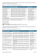
11.5.4 Breaker alarms
More information
The
Breakers, synchronisation and de-loading
chapter describes breaker handling and alarms in general.
DESIGNER'S HANDBOOK 4189340911K UK
Page 396 of 521

