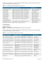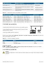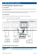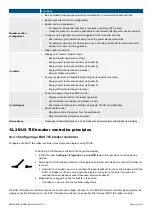
Functions
•
Bus tie breaker close sequence (with synchronisation), to connect the busbar sections
Busbar section
management
•
Busbar split and connection (configurable)
•
Busbar section management
◦
For example, independent busbars for dynamic positioning (DP) vessels
◦
A busbar section can be under switchboard control without affecting other busbar sections
•
Configure up to eight sets of power management rules for busbar sections
◦
Use CustomLogic to determine when to use the power management rules
◦
For example, when the bus tie breaker is open, the rules can specify the minimum and/or
maximum number of running gensets
•
Ring busbar connection
Counters
•
Display unit counters, to edit or reset
◦
Bus tie breaker operations and trips
◦
Energy export (active and reactive) (to busbar B)
◦
Energy import (active and reactive) (to busbar A)
◦
Energy differential (active and reactive)
◦
External breaker operations
•
Energy counters with configurable digital outputs (for external counters)
◦
Energy export (active and reactive) (to busbar B)
◦
Energy import (active and reactive) (to busbar A)
◦
Energy differential (active and reactive)
Control types
•
Power management system (PMS) control
◦
Display unit push-buttons for breaker operations
◦
Synchronisation, de-loading, and breaker control
◦
Push-button functions also possible using inputs, PICUS, and/or Modbus
•
Switchboard control
◦
Operator controls the system from the switchboard
◦
Only the controller protections are active
Redundancy
•
Redundant breaker feedback on bus tie breakers and externally controlled bus tie breakers
12.2 BUS TIE breaker controller principles
12.2.1 Configuring a BUS TIE breaker controller
Configure each BUS TIE breaker controller in the single-line diagram, using PICUS.
To add a BUS TIE breaker controller to the single-line diagram:
1. In PICUS, under
Configure > Single-line
, drag the
BTB icon
to the right place on the single-line
diagram.
2. Select the BUS TIE breaker controller on the single-line diagram, and make sure that its
Controller ID
is correct.
a. Optional: You can add one or more redundant breaker feedbacks for the bus tie breaker. Select the
BUS TIE breaker controller on the single-line diagram, and select a controller to provide the
redundant breaker feedback under
Redundant breaker feedback #
.
3. Broadcast the changes to all the controllers in the system.
•
If needed you can override the controller ready status.
The BUS TIE breaker controller measures the current and voltage on busbar A. The BUS TIE breaker controller also measures the
voltage on busbar B. Busbar A for one BUS TIE breaker controller can be busbar B for the next BUS TIE breaker controller.
DESIGNER'S HANDBOOK 4189340911K UK
Page 401 of 521

