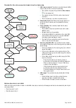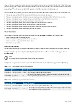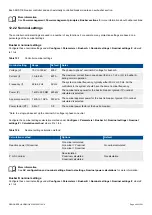
Table 12.3
Controller nominal settings
Nominal setting Range
Default Notes
Voltage (V)
10 V to 160 kV 400 V
The phase-to-phase nominal voltage for busbar B. If there is no transformer between
busbar A and busbar B, the nominal voltage for busbar B is the same as the nominal
voltage for busbar A.
Frequency (f)
48 to 62 Hz
50 Hz
The system nominal frequency, typically either 50 Hz or 60 Hz. All the controllers in
the system should have the same nominal frequency.
12.2.3 AC configuration
More information
The
AC configuration and nominal settings
chapter describes the AC configuration in general.
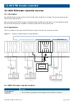
The following table shows how the general AC configuration description applies to the BUS TIE breaker controller.
Table 12.4
AC configuration for the BUS TIE breaker controller
BUS TIE breaker
General name
Busbar A
[Source]
Busbar B
[Busbar]
12.2.4 Breaker configuration
More information
See the
Breakers, synchronisation and de-loading
chapter for more information on synchronisation and breakers. This
includes the inputs and output functions and the parameters to configure.
For the BUS TIE breaker controller, the breaker abbreviation (
[*B]
) is
BTB
.
[Breaker]
refers to
Bus tie breaker
.
12.3 BUS TIE breaker controller sequences
12.3.1 Splitting the busbar
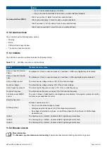
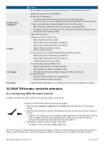
The busbar can be split into two busbar sections which operate independently by opening the bus tie breaker. The signal to open the
bus tie breaker can come from:
•
The operator can press the push-button
Open breaker
on the BUS TIE breaker controller display unit.
•
The operator can use PICUS to send an open breaker command.
•
A digital input with the
Breakers > Bus tie breaker > Command > BTB open
function.
•
An external source, like a PLC.
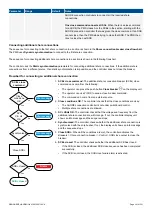
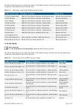
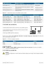
The power management system then ensures that there is enough power available for each busbar section so that they can run
independently. If there is enough power on each busbar section, the power management system de-loads the bus tie breaker. When
the bus tie breaker is de-loaded, the BUS TIE breaker controller opens the bus tie breaker.
Requirements
The power management system can only split the busbar if:
•
The following controllers are under PMS control (that is, they are not under switchboard control):
◦
BUS TIE breaker controller
◦
All connected GENSET controller(s)
◦
Connected SHAFT generator controller(s) (if present)
◦
Connected SHORE connection controller(s) (if present)
DESIGNER'S HANDBOOK 4189340911K UK
Page 403 of 521

