•
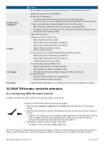
The operator can press the push-button
Close breaker
on the BUS TIE breaker controller display unit.
•
The operator can use PICUS to send an close breaker command.
•
A digital input with the
Breakers > Bus tie breaker > Command > BTB close
function.
•
An external source, like a PLC.
The power management system then synchronises the busbar sections on either side of the breaker. When the busbars are
synchronised, the controller closes the bus tie breaker.
When you close a bus tie breaker, then the two sections on either side of the bus tie breaker are joined into one section. The supply
mode after closing is required if a shaft generator or shore connection was supplying power to one of the sections before the bus tie
breaker closed.
You can set the supply mode after closing either by configuring the function on a digital input, or by selecting the option in a
parameter. The controller uses the last written value. That is, when the digital input is activated, that changes the parameter in the
controller. Similarly, the parameter is updated when it is changed and written in the controller.
Requirements
The power management system can only connect the busbar sections if, for at least one of the sections, all of the following
controllers are under PMS control (that is, they are not under switchboard control) :
•
BUS TIE breaker controller
•
SHAFT generator controller (if present and
connected
)
•
SHORE connection controller (if present and
connected
)
•
GENSET controllers for the gensets that are
connected
to the busbar
INFO
If one or more controllers in the one section are under switchboard control and connected, then the connected GENSET
controllers in the other section are forced into SEMI mode after the sections are joined.
The controller will not allow the bus tie breaker to close in any of these situations:
•
In the sections to be joined, there are one or more unknown breaker positions.
•
Shaft generators are
connected
on both sides of the breaker.
•
Shore connections are connected on both sides of the breaker, and
Multiple shore connections allowed
is
Not enabled
.
If only gensets are connected to both sections, the power management system can connect the sections, even if
Stay on SG/SC
supply
is selected.
Inputs and outputs
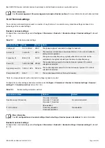
Optional: Assign the supply mode input(s) under
Configure > Input/output
. Select the hardware module, then select the input to
configure.
Table 12.6
Breaker configuration
Function
I/O
Type
Details
Additional functions > Supply
mode > Stay on DG supply
after BTB close
Digital
input
Pulse
When this input is activated, the controller changes the parameter value
under
Configure > Parameters > Local power management > Bus tie breaker
> Supply mode after BTB close > Supply mode after connecting
to
Stay on
DG supply
(see below).
Additional functions > Supply
mode > Stay on SG/SC supply
after BTB close
Digital
input
Pulse
When this input is activated, the controller changes the parameter value
under
Configure > Parameters > Local power management > Bus tie breaker
> Supply mode after BTB close > Supply mode after connecting
to
Stay on
SG/SC supply
(see below).
DESIGNER'S HANDBOOK 4189340911K UK
Page 405 of 521

