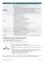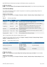
To see certain digital output functions, you must include the corresponding equipment in the single-line diagram.
Relay state
The relay state (whether it is open or closed) depends on the relay hardware, the coil state and the function (or alarm) state. The
following table shows how these combine to give the relay state.
Table 13.1
Relay state
Hardware
Coil configuration
Function (or alarm)
Relay state
Normally open
Normally de-energised
Not activated
Open
Normally open
Normally de-energised
Activated
Closed
Normally open
Normally energised
Not activated
Closed
Normally open
Normally energised
Activated
Open
Normally closed
Normally de-energised
Not activated
Closed
Normally closed
Normally de-energised
Activated
Open
Normally closed
Normally energised
Not activated
Open
Normally closed
Normally energised
Activated
Closed
The effect of the relay hardware, the coil state and the function (or alarm) state is also shown below under
Coil state
.
CAUTION
Incorrect connection of the relay, or incorrect configuration of the relay function, will cause incorrect operation.
Relay hardware
The relay hardware can be normally open or normally closed. The relay hardware returns to its normal state when the controller has
no power. The relay hardware type is shown on the hardware module faceplate.
Normally open relay hardware:
•
All PSM3.1 relays
•
IOM3.1 terminals 1,2
•
IOM3.1 terminals 4,5
•
IOM3.1 terminals 7,8
•
IOM3.1 terminals 10,11
•
All EIM3.1 relays
•
All GAM3.1 relays
•
All GAM3.2 relays
Normally closed relay hardware:
•
IOM3.1 terminals 3,2
•
IOM3.1 terminals 6,5
•
IOM3.1 terminals 9,8
•
IOM3.1 terminals 12,11
Coil state
You can configure the normal coil state in the display unit or PICUS. Under
Configure > Input/output
, select the terminals, then
select
Normally de-energised
(the default) or
Normally energised
for the
Coil state
.
DESIGNER'S HANDBOOK 4189340911K UK
Page 415 of 521


