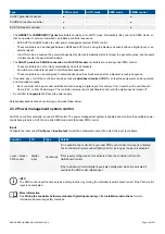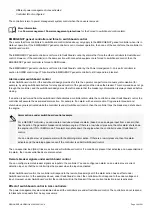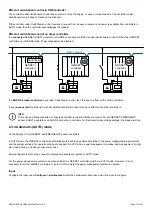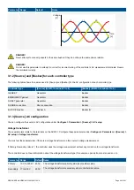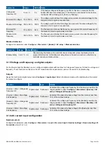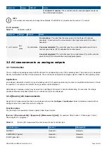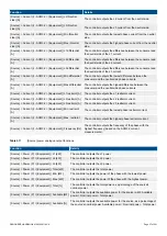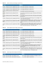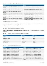
Parameter Range
Default
Notes
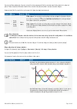
Voltage
[V]
L1
L3
L2
Time
[s]
DANGER!
Never attempt to connect gensets to the same busbar if they do not have the same phase rotation.
DANGER!
Do not use this parameter to attempt to correct for incorrect wiring of the controller's AC measurement terminals. Rewire
the terminals correctly.
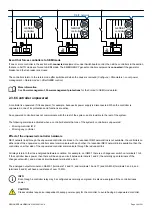
3.1.2 [Source] and [Busbar] for each controller type
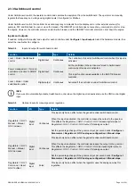
The following table shows the names used for [Source] and [Busbar] for the AC configuration of each controller type.
Controller type
[Source] (ACM3.1 terminals 5 to 8)
[Busbar] (ACM3.1 terminals 1 to 4)
GENSET
Generator
Busbar
EMERGENCY genset
Generator
Busbar
SHAFT generator
Generator
Busbar
SHORE connection
Shore connection
Busbar
BUS TIE breaker
Busbar A
Busbar B
3.1.3 [Source] AC configuration
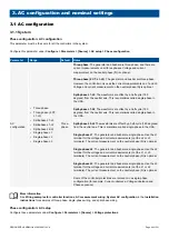
You can configure the source's AC configuration under
Configure > Parameters > [Source] > AC setup
.
Voltage transformer
These parameters relate to the terminals on the ACM3.1. Configure these parameters under
Configure > Parameters > [Source] >
AC setup > Voltage transformer
.
You must set these parameters if there is a voltage transformer on the source's voltage measurement.
If
Primary
:
Secondary
ratio is 1, the controller uses the voltage measurement without any correction for a voltage transformer.
The controller does not need information about the voltage transformer type (for example, open delta, star-star, and so on).
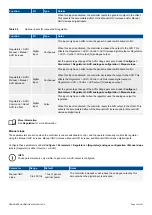
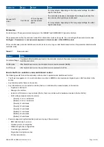
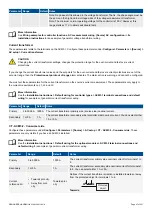
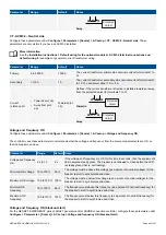
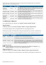
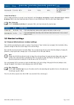
Parameter Range
Default Notes
Primary
10 V to 160 kV 400 V
The voltage transformer primary side (source side) value.
Secondary 17 to 690 V
400 V
The voltage transformer secondary side (controller side) value.
DESIGNER'S HANDBOOK 4189340911K UK
Page 46 of 521

