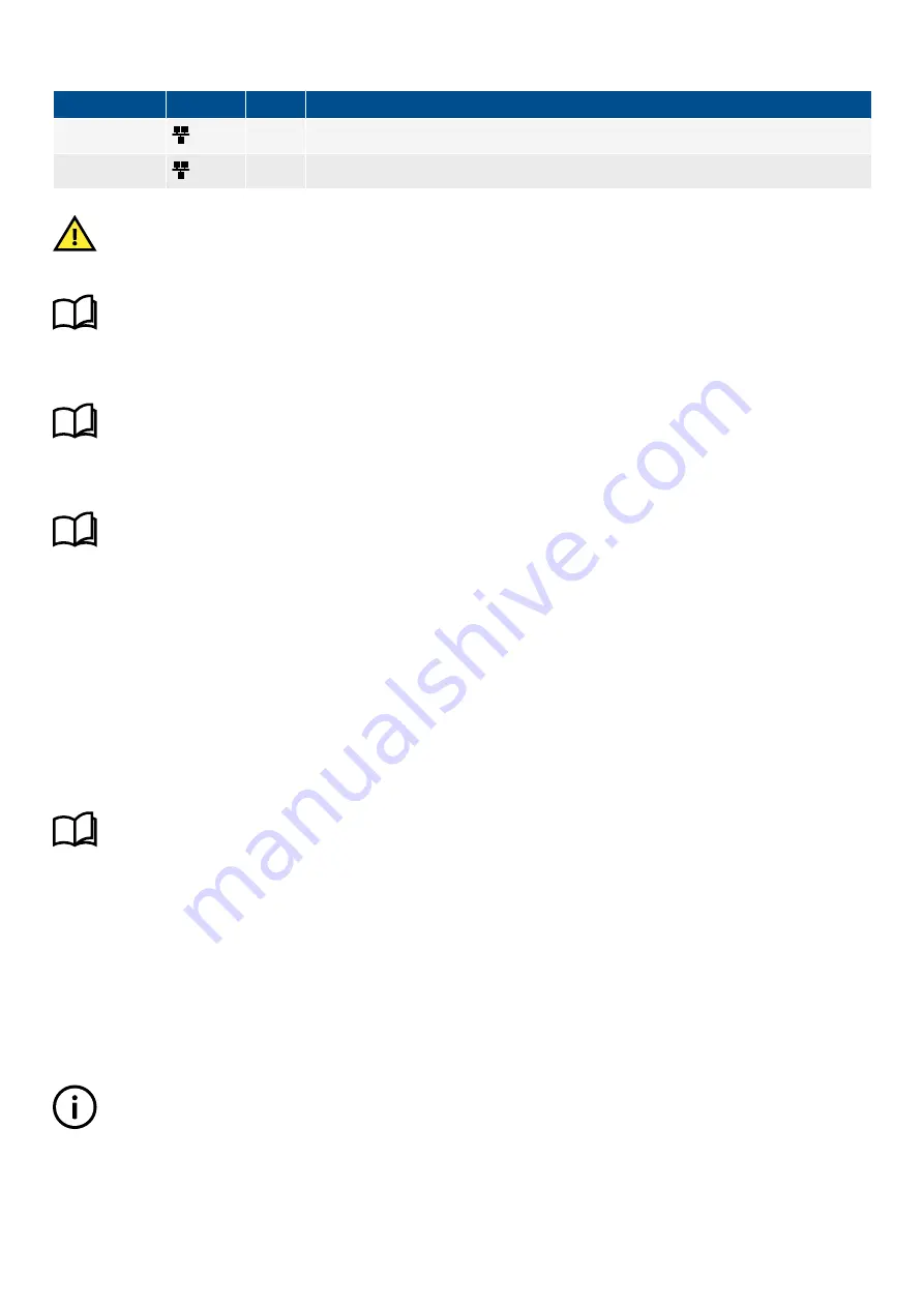
Table 13.50
Display unit Ethernet connections
Connection
Symbol
Type
Name
1
RJ45
DEIF network Ethernet connection to controller (default connection)
2
RJ45
Ethernet for additional display units
CAUTION
The display unit must be paired to a controller in the DEIF network. During commissioning, or the first time a display unit is
powered, the display unit prompts for a controller confirmation.
More information
See the
Commissioning guidelines
for more information regarding the first pair selection.
13.13.3 Frame ground characteristics
More information
See
Hardware characteristics and configuration
,
General characteristics
,
Frame ground characteristics
.
13.13.4 Power supply characteristics
More information
See
Hardware characteristics and configuration
,
General characteristics
,
Power supply characteristics
.
13.13.5 Relay output characteristics
Changeover relay, terminals 3,4,5
For future use. You cannot configure this relay.
Status OK relay, terminals 6,7
The relay output on terminals 6,7 is used for the display unit
Status OK
. If the display unit loses communication with the controller, or
an internal failure occurs, then the display unit deactivates the relay.
You cannot change the relay configuration. The relay is always energised when the communication is OK.
More information
See
Hardware characteristics and configuration
,
General characteristics
,
Relay output characteristics and
configuration
for more information.
13.14 DEIF Ethernet network
13.14.1 Communication
The controllers communicate with each other to manage the system over the DEIF network, an Ethernet network.
For communication redundancy, the controllers can be connected in a ring. If there is a disruption or failure, the DEIF proprietary ring
protocol changes the communication path within 100 milliseconds.
INFO
Controllers must only be connected with
Network chain
or
Network ring
configuration. Do not include display units or other
equipment in the chain or ring.
DESIGNER'S HANDBOOK 4189340911K UK
Page 470 of 521


