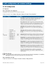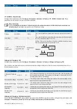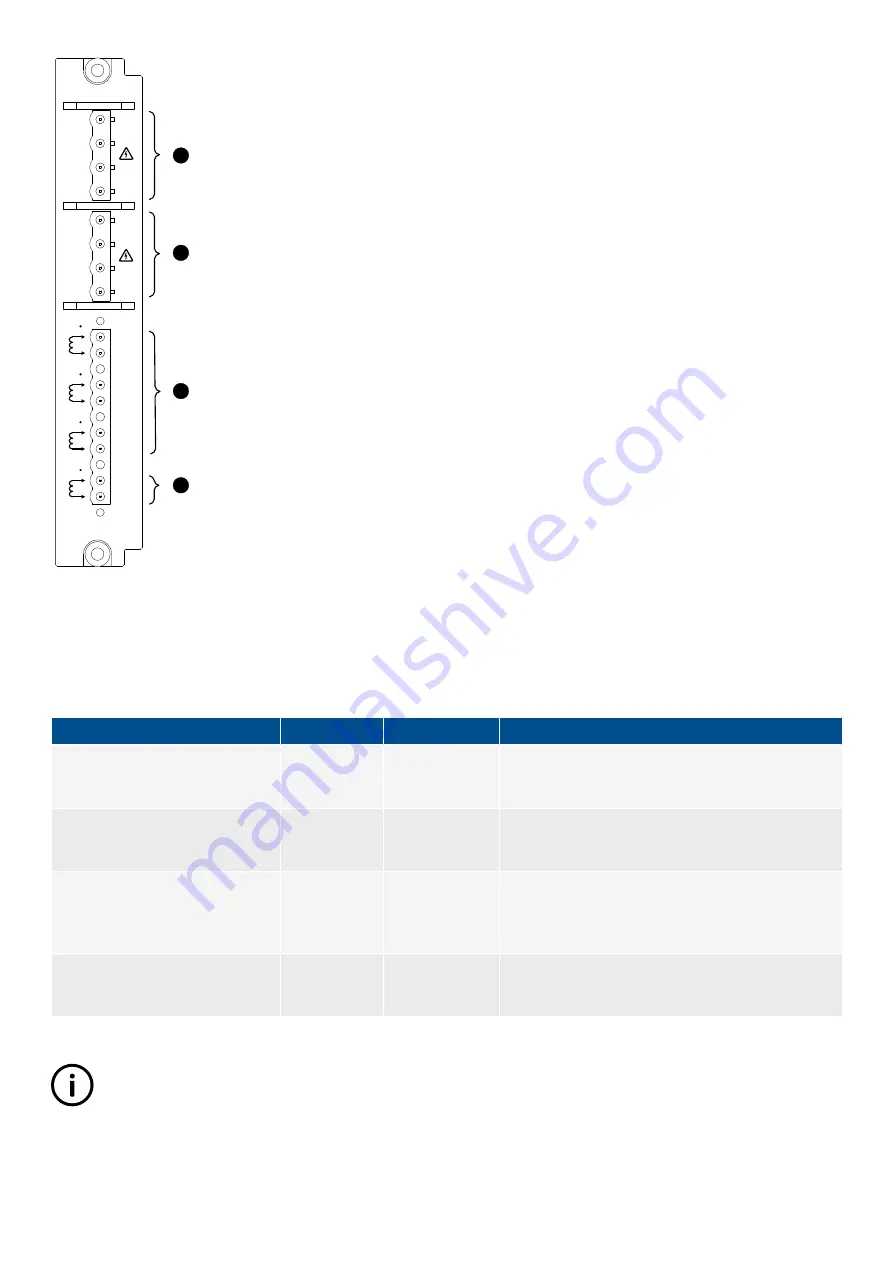
L3
S1
S2
L2
S1
S2
L1
S1
S2
L1
L1
L2
L2
L3
L3
N
N
ACM3.1
*
S1
S2
4
1
2
3
4
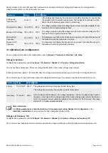
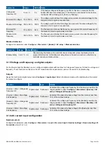
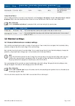
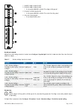
1. [Busbar] voltage measurements
2. [Source] voltage measurements
•
For example: GENSET controller: The voltage at the genset
3. [Source] current measurements
•
For example: GENSET controller: The current from the genset
4. 4th current measurement
•
For example: Earth current
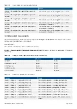
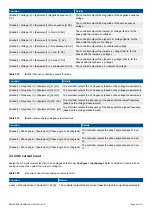
Inputs and outputs
Assign the nominal settings inputs and outputs under
Configure > Input/output
. Select the hardware module, then select the input/
output to configure.
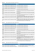
Table 3.1
Nominal settings inputs and outputs
Function
I/O
Type
Details
Local > Nominal settings >
Controller nominal setting > Nominal
setting #
Digital input
Pulse
The controller changes the active nominal setting group
to the nominal setting group assigned to the digital
input.
Local > Nominal settings >
Controller nominal setting > Nominal
setting # selected
Digital output
Continuous
Activated if the active nominal setting group is the same
as the nominal setting group configured to the output.
Local > Nominal settings >
Controller nominal setting > Nominal
setting #
Analogue input
Supervised
binary input
The controller changes the active nominal setting group
to the nominal setting group assigned to the analogue
input. The input signal is treated by the controller as a
pulse signal.
Local > Nominal settings >
Controller nominal setting > Nominal
setting # selected
Analogue
output
0 to 3
The controller outputs a number correlating to the
active nominal setting group. Where
Nominal setting 1
is zero.
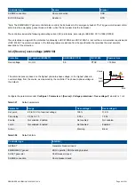
Parameters
INFO
See the chapter for the specific controller type for the nominal setting parameters for voltage, current and generator speed
(if applicable).
Configure these parameters under
Configure > Parameters > Local > Nominal settings > Controller nominal setting
.
DESIGNER'S HANDBOOK 4189340911K UK
Page 52 of 521


