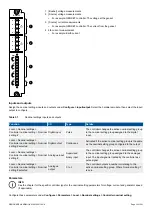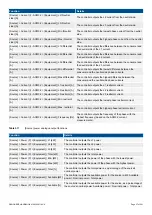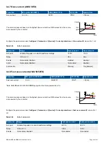
Negative sequence voltages arise when the virtual representation of the phase rotation for an
unbalanced system appears negative.
Negative sequence voltages can occur where there are single phase loads, unbalanced line
short circuits and open conductors, and/or unbalanced phase-to-phase or phase-to-neutral
loads.
The alarm response is based on the estimated phase-to-neutral voltage phasors, as measured
from the source.
Controller types: This alarm is present in the GENSET and BUS TIE breaker controllers.
L1
L3
L2
Configure the parameters under
Configure > Parameters > [Source] > Voltage protections > Negative sequence voltage
.
Table 3.33
Default parameters
Parameter
Range
Negative sequence voltage
Set point
1 to 100 % of nominal voltage
5 %
Time delay
0.1 s to 1 h
0.5 s
Enable
Not enabled, Enabled
Not enabled
Action
Warning
3.4.6 Zero sequence voltage (ANSI 59Uo)
Protection
IEC symbol (IEC60617)
ANSI (IEEE C37.2)
IEC 61850
Operate time
Zero sequence voltage
59Uo
PZOV
< 200 ms*
*Note: This operate time includes the minimum user-defined delay of 100 ms.
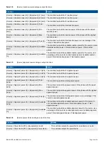
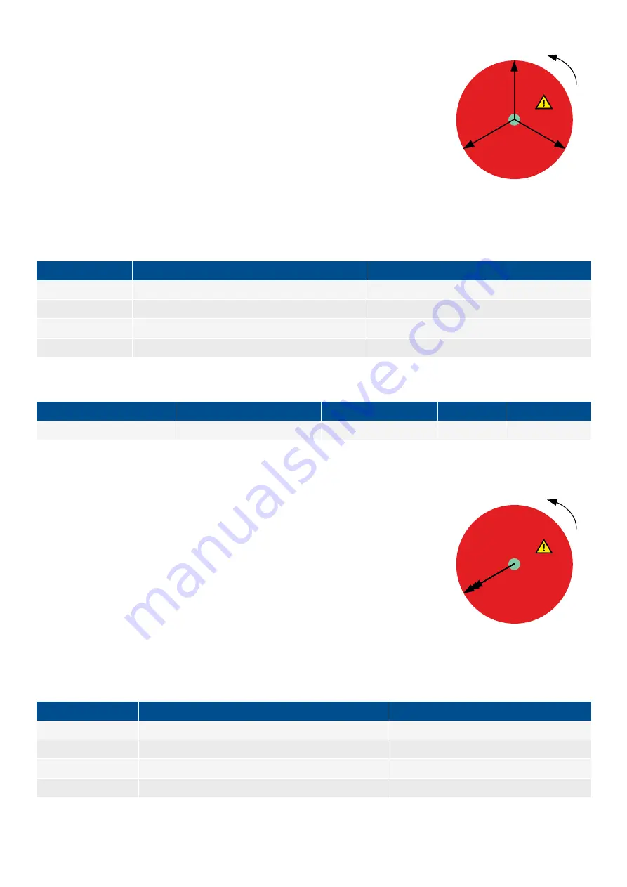
Zero sequence voltages arise when the phases rotation is positive, but the vector zero value
(star point) is displaced. This zero sequence voltage protection can be used instead of using
zero voltage measurement or summation transformers (zero sequence transformers).
This protection is used for detecting earth faults.
The alarm response is based on the estimated phase-to-neutral voltage phasors, as measured
from the source.
Controller types: This alarm is present in the GENSET and BUS TIE breaker controllers.
L1
-L2
-L3
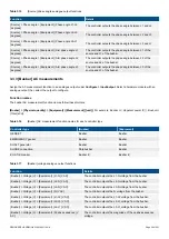
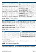
Configure the parameters under
Configure > Parameters > [Source] > Voltage protections > Zero sequence voltage
.
Table 3.34
Default parameters
Parameter
Range
Zero sequence voltage
Set point
1 to 100 % of nominal voltage
5 %
Time delay
0.1 s to 1 h
0.5 s
Enable
Not enabled, Enabled
Not enabled
Action
Warning
DESIGNER'S HANDBOOK 4189340911K UK
Page 65 of 521

