Test
activated
Engine start
sequence
Close generator
breaker
Open generator
breaker
Engine stop
sequence
Controller to
mode after test
GB closed
No
Yes
GB opened
No
Yes
Stop
sequence
OK
No
Yes
Start
sequence
OK
No
Yes
Test
timer
expired
No
Yes
Alarm
Test timer
starts
Alarm
Alarm
Alarm
Open tie
breaker
Tie breaker
opened
No
Yes
Close tie
breaker
Tie breaker
closed
No
Yes
Alarm
Alarm
G
Emergency
load
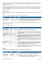
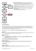
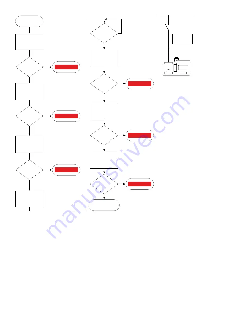
1. The controller starts the emergency
genset when the TEST function is
activated.
2. The controller synchronises and
closes the genset breaker.
3. The controller opens the tie breaker
between the emergency busbar and
the main busbar.
4. The controller starts the test timer.
5. After the test timer runs out, the
controller synchronises and closes
the tie breaker.
6. The controller de-loads and opens
the emergency genset breaker.
7. The emergency genset cools down
and then stops.
8. The EMERGENCY genset controller
changes to the mode specified in
the
After EDG test
parameter.
No governor control
The load take-over test is modified if the controller does not control the governor (and therefore cannot synchronise with the main
busbar). Instead of synchronising, the EMERGENCY genset controller opens the tie breaker, and immediately after that closes the
generator breaker.
9.7 Emergency genset configurations
9.7.1 Overview
The emergency genset can either be part of the power management system, or a stand-alone genset.
The single-line diagram for the EMERGENCY genset controller determines whether the emergency genset is part of the power
management system or stand-alone.
DESIGNER'S HANDBOOK 4189340911K UK
Page 336 of 521


