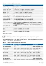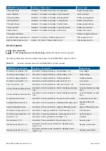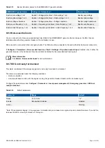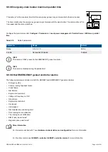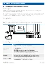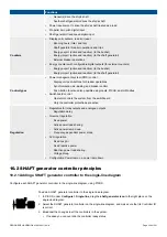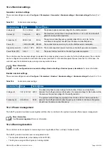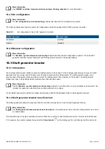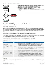
Function
I/O
Type
Details
[Source] > AVR >
Trip AVR
Digital
output
Continuous
When this output is configured it is possible to assign alarm actions that trip the
AVR.
When an alarm with a
Trip AVR
action activates, the
Trip AVR
digital output
activates and stays activated until all alarms with a
Trip AVR
action are resolved.
When the output is active, the controller pauses AVR regulation.
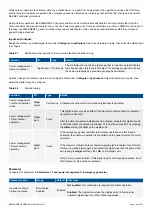
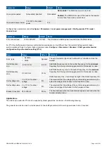
Table 9.9
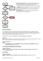
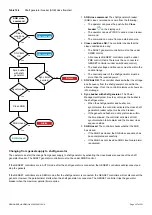
Trip AVR sequence diagram
Trip
AVR
(2)
Number of
trip AVR
alarms
(1)
1
0
2
To trip the AVR:
1.
Number of trip AVR alarms
: The number of active
alarms with a
Trip AVR
(or similar) alarm action.
2.
Trip AVR
:
[Source] > AVR > Trip AVR
(digital output).
The controller activates this output until all alarms with
a
Trip AVR
(or similar) alarm action are not active.
9.9 EMERGENCY genset controller protections
9.9.1 EMERGENCY genset controller alarms
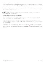
INFO
These alarms are in addition to the AC protections and other alarms for PPM 300 controllers.
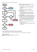
INFO
During a blackout, the suppressed alarms are shown as
Warnings
.
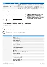
Alarms
Engine
Emergency stop
Overspeed (2 alarms)
Under-speed (2 alarms)
Governor regulation error
Power ramp up error
Power ramp down error
Crank failure
Primary running feedback failure
Start failure
Stop failure
EIM3.1 # relay 4 wire break (where # is 1 to 3)
Engine stop (external)
Engine start (external)
Start enable removed during start
Total running hours notification
Trip running hours notification
Magnetic pickup wire break
DESIGNER'S HANDBOOK 4189340911K UK
Page 347 of 521


