CAUTION
To prevent the current measurements from being swapped around, DEIF recommends that the current measurement
terminals are fitted with encoding pins. Check that the wiring to the terminals has not been swapped around during
installation if encoding pins are used.
See
Mounting current encoding pins
for an example of how the encoding pins
can be placed.
13.6.3 Current measurement characteristics
The ACM3.2 has two sets of terminals for current measurement. The first set of terminals (1 to 6) measures the current at the
consumer side of the generator. The second set of terminals (7 to 12) measures the current at the neutral side of the generator. The
ACM3.2 uses these measurements for logging, alarms and protective functions relating to differential current protection in the
system.
13.7 Input/output module IOM3.1
13.7.1 Input/output module IOM3.1
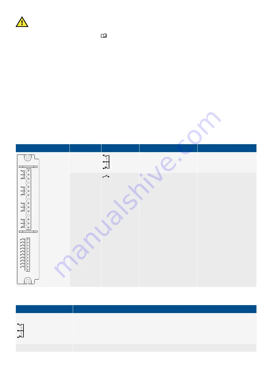
The input output module has four changeover relay outputs, and 10 digital inputs. These I/Os are all configurable.
Table 13.22
IOM3.1 terminals
Module
Count
Symbol
Type
Name
1
2
3
4
5
6
7
10
9
8
11
12
13
14
15
16
17
21
20
19
18
22
23
COM
IOM3.1
4
Relay output
Configurable
10
Digital input
Configurable
Table 13.23
IOM3.1 technical specifications
Category
Specification
Relay outputs
Relay type: Electromechanical
Electrical rating and UL/cUL Listed: 250 V AC or 30 V DC, and 6 A, resistive; B300, pilot duty
(B300 is a power limit specification for inductive loads)
Altitude derating from 3,000 to 4,000 m (9,842 to 13,123 ft): Maximum 150 V AC phase-to-phase
Voltage withstand: 250 V AC
Digital inputs
Bipolar inputs
DESIGNER'S HANDBOOK 4189340911K UK
Page 437 of 521


