The alarm is always enabled, and the alarm action is
Warning
. The alarm parameters are not visible.
13.12 Processor and communication module PCM3.1
13.12.1 Processor and communication module PCM3.1
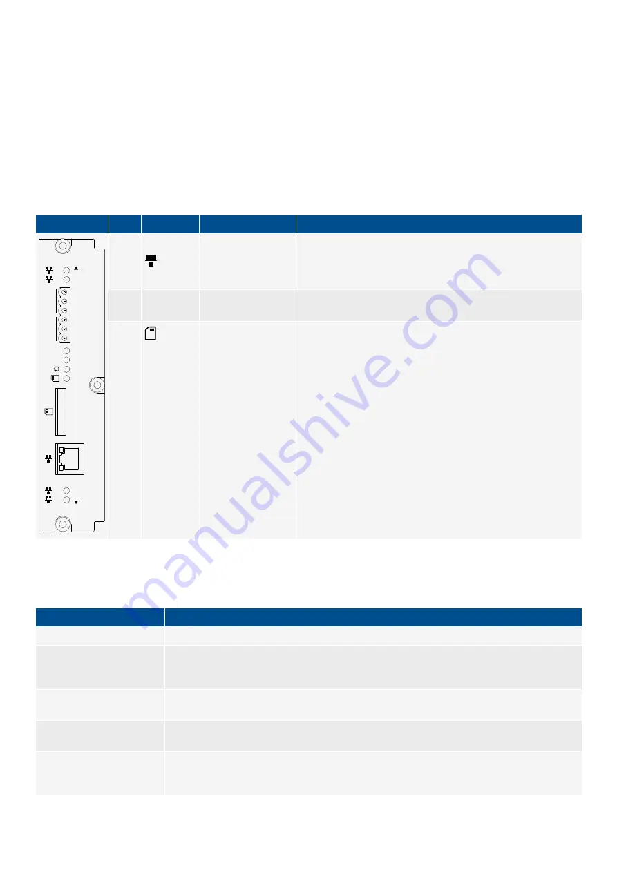
The processor and communication module has the controller's main microprocessor, which contains and runs the controller
application software. It includes the Ethernet switch to manage the controller Ethernet connections, with five 100BASE-TX Ethernet
connections. It has a
Self-check OK
LED. It also has two sets of CAN bus terminals and houses the SD card. The PCM3.1 performs
time synchronisation with an NTP server.
Table 13.44
PCM3.1 terminals
Module
Count Symbol
Type
Name
1
2
3
4
5
6
CAN-A
PCM3.1
CAN-B
CAN-A
CAN-B
1
2
3
4
5
L
H
H
L
5
Ethernet (RJ45)
Network and DEIF network
(The LEDs are on the front of the hardware module. Two of the
connections are at the top of the hardware module, one on the
front, and two at the bottom.)
2
H, CAN-A, L
H, CAN-B, L
CAN bus connection CAN bus (for future use)
1
SD card*
External memory
*Note: To meet the temperature and EMC specifications, you must use an industrial grade SD card.
Table 13.45
PCM3.1 technical specifications
Category
Specification
CAN terminals
Voltage withstand: ±24 V DC
Galvanic isolation
Between CAN A and other I/Os: 600 V, 50 Hz for 60 s
Between CAN B and other I/Os: 600 V, 50 Hz for 60 s
Between Ethernet ports and other I/Os: 600 V, 50 Hz for 60 s
Battery
CR2430 3V rated for operation at -40 to 85 °C (-40 to 185 °F). This battery can be changed.
Not
a
standard CR2430 battery.
Battery life
Design life of the timekeeping battery is 10 years. This is reduced if the ambient temperature is
over 40 °C (104 °F).
Communication
connections
CAN communication terminals: Standard 45° plug, 1.5 mm
2
Wiring: 0.5 to 1.5 mm
2
(28 to 16 AWG), multi-stranded
DESIGNER'S HANDBOOK 4189340911K UK
Page 463 of 521


