background image


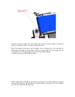
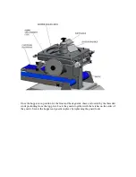
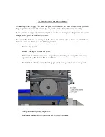
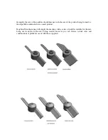
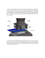
Position  the  chosen  paddles  onto  the  paddle  shaft  at  the  top  of  the  machine,  ensuring  the 
keyways are aligned, and secure in place with paddle knob. 
 
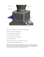
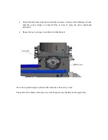
Ensure  the  hopper  sealing  ring  is  pressed  firmly  into  its  retaining  slot  in  the  machine  top. 
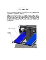
Slacken the four hopper securing knobs on the top of the machine. Place the hopper into the 
top machined recess on the hopper seal and rotate such that the hopper 
securing lugs engage with the threaded studs.  


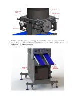
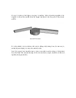
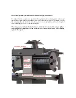
NOTE - The hopper is handed to ensure correct positioning, one of the hopper lugs is longer 
than the other three lugs, the threaded studs, (left hand stud as seen below) is set in a different 
position to accommodate the longer lug. 
 

Summary of Contents for FORMATIC D12,000

Page 1: ...FORMATIC D12 000 Instruction manual Gibson Street Leeds Road Bradford West Yorkshire England BD3 9TR Telephone 44 0 1274 668771 Fax 44 0 1274 665214...

Page 2: ...chnical Specification 3 Installation Preparation for Production 4 Operating the machine 5 Cleaning 6 Safety 7 Maintenance 8 Fault Finding Guide 9 Recommended Spares List 10 Wiring Diagrams 11 Optional...

Page 3: ...textures and consistencies the Formatic D12 000 uses synchronised paddles to gently press mixture into the required form shape in both drums of the machine Assisted by the wire drum scrapers the forme...

Page 4: ...40v 50hz AC Power 1760w Product Envelope L 140mm x W 135mm x D 6mm to 24mm 6mm to 34mm special Product Output 12 000 per hour Hopper Capacity 200 Litres Noise Emissions do not exceed 70 dB at workstat...

Page 5: ...to lift the ejector set over the cam Fit the paper cam guard over the drum on the end of the shaft and secure with spanner Repeat the procedure for both drums Locate the front conveyor platform denote...

Page 6: ...top Slacken the four hopper securing knobs on the top of the machine Place the hopper into the top machined recess on the hopper seal and rotate such that the hopper securing lugs engage with the thre...

Page 7: ...the front and back guards these are located by the threaded studs protruding from the top plate Lock the guards together with the latches on the sides of the guards Secure the hopper and guards in pl...

Page 8: ...n start button Check for smooth operation of the paddles drum and conveyors To stop the machine press the red stop button The working position of the scraper although factory set can be adjusted manua...

Page 9: ...water tank remove the water pipe from the tank the pipe is loose within the tank remove the water tank from within the cabinet fill the water tank with 2 to 2 litres of clean water replace the tank an...

Page 10: ...cted and switched on The guards are correctly positioned the guards contain interlocks that prevent the machine from working unless they are situated correctly There are no obstructions preventing the...

Page 11: ...rt button to operate To adjust the thickness and weight of the finished product the variation available being between 6mm and 34mm use the following routine Remove the guards Remove the paper attachme...

Page 12: ...the correct weight is achieved This is done by using the above mentioned procedure Ensure there are no large hard objects within the mix Once the required weight is achieved the machine is then ready...

Page 13: ...formed i e small paddle combination for a small product Deighton Manufacturing will supply the machine with a series of paddles suitable for the mix being used and the form sizes being created however...

Page 14: ...pressure paddles If in the unlikely event problems still occur in filling and forming it may be necessary to modify the mix slightly to achieve the desired results Note The scraper wire should be kep...

Page 15: ...ponents and can be cleaned using hot soapy water the machine can be hosed down but not using a pressure washer Cleaning the Machine Dismantle the machine in the reverse order to assembly Wash all part...

Page 16: ...led operated and maintained by trained and authorised personnel Isolate the machine when changing the drum Do not run the machine without the drum guard being in position Isolate the machine before cl...

Page 17: ...d and sockets so preventing water ingress Check condition of belt and rollers Check condition of plastic scraper wire Check there is sufficient plastic scraper wire on either end of scraper wire screw...

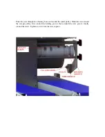
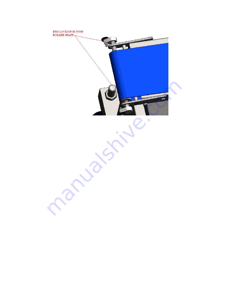
Page 18: ...re the belt is not catching anywhere or slipping on the drive roller The alter the belt tension lift the conveyor tensioners upwards unlock the locking nose bushes with a spanner then move the conveyo...

Page 19: ...the conveyor belt contains a tracking strip on the underside of the belt this must be pulled free of the groove in the drive roller The conveyor belt can now be removed replaced To replace the conveyo...

Page 20: ...locking screw body and lock up screw it is possible to rotate the scraper pulleys by hand run wire down groove in scraper pulley and wind a length of wire in holding groove 1 to 2 metres in length Th...

Page 21: ...rough the cleaning boss and around the small pulley Wind the wire around the scraper pulley first around the holding groove than around the wire groove finally around the screw Tighten screw to lick t...

Page 22: ...Standard Belt 700 FD1000 Extended Belt 1200 FD1001 Plastic Scraper Wire FD1181 Hopper Seal F117C Paddle Knob F130 Start Button F1004 Start button Boot F1004 Start Button Contact Block F1006 Emergency...

Page 23: ...10 WIRING DIAGRAMS...

Page 24: ......

Page 25: ......

Page 26: ......

Page 27: ...lso be supplied by Deighton Manufacturing are loaded onto a cartridge and then released onto the base of the formed product before been ejected onto the conveyor If a paper attachment is fitted and pa...

Page 28: ......

Page 29: ...Position of the paper relative to the form can be adjusted by simply rotating the paper attachment cam using the drum pin as a locating position...

Page 30: ...Conveyors The D12 000 can be fitted with extended conveyors Standard conveyor length is 700mm the extended conveyors are 1200mm long...

Page 31: ...12 Dolomite AB Water chiller Installation and Instruction Manual...

Page 32: ...rt up procedure 5 Fault Finding 6 Refrigeration system fault diagnosis and test procedure 7 Dolomite AB water chiller top assembly exploded drawing 8 Dolomite AB water chiller part list 9 Dolomite AB...

Page 33: ...perate Adhere to all warnings on the unit and in this manual Follow all operating and user instructions Only if the beverage cooler is properly installed will trouble free operation and customer satis...

Page 34: ...onnect electrical connection between the chiller and the host machine Disposal of Scrap Units It is illegal to scrap a refrigeration unit Before a unit can be scrapped it must first have the refrigera...

Page 35: ...ient water in water tank Check for any obvious blockages No cooling Freeze or intermittent freezing Refer to the refrigeration fault finding for partial or complete freeze up Partial loss of charge If...

Page 36: ...nst the compressor shell If both fan and compressor are running this could indicate a loss of refrigerant or a blockage in the system In the case of a blockage the unit will normally be very hot and m...

Page 37: ...he relay and thermal trip unit and test for continuity across the main windings pins A and C a reading of 37 6 ohms should be achieved Test for continuity across the start windings pins A and B a read...

Page 38: ...rozen up Check the operation of the thermostat The compressor should switch OFF as soon as the temperature of the heat exchanger has reached the required temperature If the compressor keeps running th...

Page 39: ...Dolomite AB water chiller top assembly exploded view...

Page 40: ...umber 1 Male IEC Plug 5 05 2 Thermostat 17 99 3 Recess door Pull 17 40 4 Condenser 5mm ID X 8mm OD clear tube 16 03 5 Condenser motor 16 11 6 Snapper Hose Clip 16 16 7 5mm ID X 8mm OD clear tube 16 15...

Page 41: ...Current 6 4 amps Materials Body Powder coated zintec steel Product coil 304 Stainless steel Evaporator 304 Stainless steel Insulation Type In situ polyurethane Refrigeration system Condenser fan 120m...

Page 42: ...0MB Displacement 4 06cc Recovery at 100C 250 kcal hr Start current 6 4A Power consumption at 100C 170 W Voltage range 198 264 volts 50Hz Start winding at 200C 19 48ohm Run winding at 200C 18 76ohm Loc...

Page 43: ...C and regulation EC 1935 2004 on materials and articles in contact with food Machine Description D12 000 FORMATIC MACHINE Serial Number Manufactured By Deighton Manufacturing UK Ltd Gibson Street Leed...

Reviews: