background image

Regulatory Notices 

Europe

Hereby, deister electronic GmbH declares that this equipment - if used according to the in-
structions - is in compliance with the essential requirements and other relevant provisions
of the RTTE Directive 1999/5/EC.

A full declaration of conformity can be requested at:

info@deister-gmbh.de

Approved for use in all European countries.

FCC Digital Device Limitations

Radio and Television Interference

This equipment has been tested and found to comply with the limits for a Class A digital
device, pursuant to Part 15 of the FCC rules. These limits are designed to provide reason-
able protection against harmful interference when the equipment is operated in a commer-
cial environment. This equipment generates, uses and can radiate radio frequency energy
and, if not installed and used in accordance with the instruction manual, may cause harm-
ful interference to radio communications. Operation of this equipment in a residential area
is likely to cause harmful interference, in which case the user will be required to correct the
interference at his own expense. This device complies with Part 15 of the FCC rules. Opera-
tion is subject to the following two conditions: (1) This device may not cause harmful interfer-
ence, and (2) this device must accept any interference received, including interference that may
cause undesired operation. In order to maintain compliance with FCC regulations, shielded
cables must be used with this equipment. Operation with non-approved equipment or un-
shielded cables is likely to result in interference to radio and television reception.
Caution! Changes or modifications not expressly approved by the manufacturer could void
the user´s authority to operate this equipment.

FCC Notice

To comply with FCC Part 15 rules in the United States, the system must be professionally
installed to ensure compliance with the Part 15 certification. It is the responsibility of the
operator and professional installer to ensure that only certified systems are deployed in the
United States. The use of the system in any other combination (such as co-located anten-
nas transmitting the same information) is expressly forbidden.

FCC Radiation Exposure Statement

This equipment complies with the FCC radiation exposure limits set forth for an uncon-
trolled environment. This equipment should be installed and operated with minimum dis-
tance of 20 cm between the radiator and the human body.

2

Zulassung_wi_en_ts_tsu-200_pro_v140205_te_bf

Summary of Contents for TranSpeed TSU 200

Page 1: ...Art 896215 Zulassung_wi_en_ts_tsu 200_pro_v140205_te_bf TSU 200 Long Distance Reader Wiring and Installation Instructions...

Page 2: ...Opera tion is subject to the following two conditions 1 This device may not cause harmful interfer ence and 2 this device must accept any interference received including interference that may cause u...

Page 3: ...during installation operation and maintenance of the electronic devices and components respectively Therefore we disclaim liability and reject responsibility for any losses damages or costs that are c...

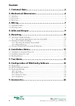
Page 4: ...unting with ball joint bracket LRM1 11 5 2 2 Direct Mounting 11 5 3 Function Principle and Environmental Influences 12 6 Installation Notes 13 6 1 Installation on the side of the road 13 6 2 Installat...

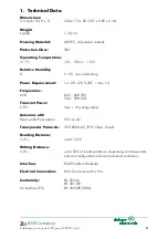
Page 5: ...EU 902 928 US Transmit Power E R P max 1 W configurable Antennas with Beam width Polarization 90 circular Transponder Protocols ISO18000 6 C EPC Class1 Gen2 Reading Distance m ft up to 7 23 Writing Di...

Page 6: ...2 Mechanical Dimensions All Dimensions in mm inch 2 1 Side View 2 2 Front View 6 Zulassung_wi_en_ts_tsu 200_pro_v140205_te_bf...

Page 7: ...ing the earth terminal 1 2 The earth terminal is supplied with the unit and can be installed at the prepared location when needed for example when the unit is installed outdoors Zulassung_wi_en_ts_tsu...

Page 8: ...male with 4 pins Pin assignment is as follows PIN Description 1 Vcc 2 RS485 A 3 GND 4 RS485 B Because of the line resistance certain cable lengths should not be exceeded The data wires 485 A and 485...

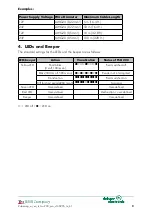
Page 9: ...the beeper are as follows LED beeper Action Visualisation Status of TSU 200 Yellow LED Short blinks 3 s off 100 ms on Field switched off Blinks 300 ms off 500 ms on Reader not interrogated Constant on...

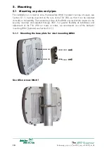
Page 10: ...ically or horizontally The serrated rear face of the LRM3 ensures that the reader can be securely mounted and adjusted through 360 For greater flexibility of installation and adjustment of the TSU 200...

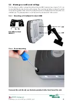
Page 11: ...the reader in any desired position Both ends of the ball joint bracket are ball beared and connected via a rotatable axis The desired position can be fixed with the included 3 8 Allen wrench 5 2 1 Mo...

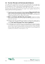
Page 12: ...be possible but will reduce the reading range depending on the condition of the material 2 Water ice and snow will absorb the carrier signal Therefore the installer has to make sure that the front of...

Page 13: ...t 6 2 Installation above the road The reader should not be installed higher than 3 0 m 9 8 ft above the road The distance from the reader to the groundloop should be in the range of 1 5 m 2 5 m 4 9 8...

Page 14: ...xample reflections on the ground can increase the maximum reading range Walls which are next to a reader and a different transponder orientation will lead to a deformation of the reading field It is t...

Page 15: ...ivation the antenna is first automatically adjusted During this adjustment there must not be any object directly in front of the antenna Following this for a period of five minutes each transponder in...

Page 16: ...f the reader is carried out by the SNG3 as long as it is connected to a power supply unit itself To do so a special wall power supply is available optional also see 9 Accessories The drivers needed ca...

Page 17: ...upply to SNG3 2 Start configuration software WebConfig 3 Select USB Serial Port 4 Click on Device Search addresses 5 Software searches for the reader which is connected to the selected COM Port 6 Afte...

Page 18: ...and hardware version HW of device Region Region the device is authorized for Hardware configuration Hardware configuration code of device Note The picture shows the frequency settings for a European...

Page 19: ...d by parameter tag timeout Anti collision Operating mode in case there is more than one tag in the field single shot Operating mode for reading tag data in case there is only one tag in the field The...

Page 20: ...ler Referenz nicht gefunden Fehler Referenz nicht gefunden Recommendation for configuration of UHF readers EU only If several readers are installed close together e g entry and exit lanes then channel...

Page 21: ...W 2 952 6 MHz 4 00 W 3 952 8 MHz 4 00 W 4 953 0 MHz 4 00 W 5 953 2 MHz 4 00 W 6 953 4 MHz 4 00 W 7 953 6 MHz 4 00 W Singapore Channel No Frequency E R P 1 920 25 MHz 2 00 W 2 920 75 MHz 2 00 W 3 921...

Page 22: ...W 50 927 50 MHz 2 00 W China Channel No Frequency E R P 1 920 625 2 00 W 2 920 875 2 00 W 3 921 125 2 00 W 4 921 375 2 00 W 5 921 625 2 00 W 6 921 875 2 00 W 7 922 125 2 00 W 8 922 375 2 00 W 9 922 62...

Page 23: ...n and United Kingdom output voltage 12 VDC 1 25 A Friwo plug 06757 000 AC DC Power Supply Power supply for c rail mounting input voltage 90 260 VAC 50 60 Hz output voltage 24 VDC 2 5 A 06756 000 SNG3...

Page 24: ...0110 Tel 1 703 368 2739 Fax 1 703 368 9791 info us deister com Singapore Coselec Pte Ltd 339158 06 12 14 Singapore Blk 28 Kallang Place info sg deister com 65 6741 5200 65 6741 6200 Benelux deister el...

Reviews: