Storage / Refresh
continued
7. All requested information on “Refresh Record Form” in
Appendix A should be completed for each refresh charge.
8. Cells shall not be stored beyond 12 months. Storing beyond 12
months will affect warranty.
9. If the storage / refresh requirements cannot be met, contact
East Penn Reserve Power Product Support Department for
alternate instructions.
INSTALLATION
General
Caution should be taken when installing batteries to ensure no
damage occurs. The battery string cabinet, tray, rack, etc. shall
be inspected for sharp edges that could cause damage to the
battery casing. Batteries shall not be dropped, slid, or placed on
rough or uneven surfaces such as tray lips or grated flooring.
Mishandling of batteries could result in equipment damage or
human injury. East Penn will not be liable for damage or injury as
a result of mishandling or misuse of the product.
Grounding
When grounding the battery string, proper techniques should be
applied per electrical standards, such as NEC and/or local codes
as well as User Manual of specific application.
Note:
Battery system grounding and/or individual module
grounding, if required, is the installer’s responsibility.
Racks
Assemble racks in accordance with intended arrangement, align
with a level and bolt to floor. Consult applicable rack assembly
instructions for specifics.
Electric Code for Maintenance Access
Refer to ANSI/NFPA-70 National Electric Code for access and
working space requirements around the battery. A minimum of 36"
aisle space is required in front of the battery system for service
and inspection.
Hardware Torque/Retorque Requirements
ELECTRICAL CONNECTION
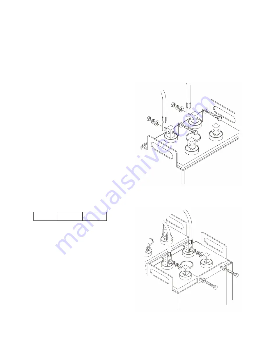
Connector / Cable Assembly
1. The contact surfaces of each individual post on every cell has
been cleaned and coated with a thin film of NO-OX-ID “A”
grease at the factory. Ensure the contact surfaces are free of
dust or dirt prior to assembly. Re-application of NO-OX-ID “A”
grease may be required if post cleaning is required.
2. Connectors/cable lugs supplied with cells. It is recommended
all connectors/cables be coated with a thin film of NO-OX-ID “A”
grease.
3. Install the cables loosely to allow for final alignment. Spacing
between cells should be a minimum of 0.50” (12.7mm) for even
airflow around cells.
4
Bolt Size
Torque / Re-torque
1/4-20
125 in lb
14.1 Nm
SYSTEM INSTALLATION
Cell Installation
Assemble system per the following details.
CAUTION: Never lift more than one cell at a time.
1. Ensure sufficient space has been allowed for proper and safe
battery installation and maintenance.
2. If cells are to be installed on a rack or cabinet, follow rack/
cabinet manufactures instructions for correct installation.
3. Batteries may be installed with posts in a vertical or horizontal
position. When installing in horizontal or vertical position, ensure
battery post are provided with ample clearance from metal parts
of rack/cabinet.
4. For multipost batteries (17 to 33 plate) a connector is to be in-
stalled at the battery system positive and negative end of each
multiple cell configuration. This connector is used to electrically
tie all same polarity posts together.
Summary of Contents for Unigy II AVR45 Series
Page 11: ...APPENDIX E 11 ...


