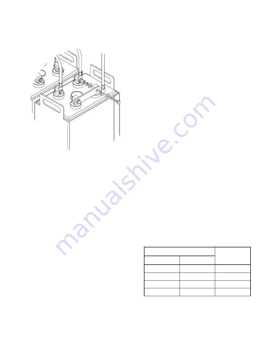
5. Charging / load cable(s) should be tin or lead plated copper lugs
able to accept a 1/4 –20 bolt. Cable lugs should be coated with
a thin film of NO-OX-ID “A” grease. System connecting cables
can be attached to any battery post of the multipost connector.
System connecting cable(s) supplied by others.
Select cable size based on current carrying capability and
voltage drop.
Select cable size based on current carrying capability and
voltage drop.
Cable size should not provide a greater voltage drop between the
battery string and operating equipment than required. Excessive
voltage drop in cables will reduce the desired reserve time and
power from the battery string.
Cable sizing is the responsibility of site electrical engineer.
SYSTEM OPERATIONS
Charger Voltage
2.25 V per battery ± 0.01 @ 77°F (25°C)
When setting the float voltage on the charger, the battery string
should be set to float at the required cell float voltage times the
number of cells per battery string. The charger must be able to
maintain the battery string voltage within ± 0.5% of the desired
level at all times.
Charge Current
Charge current should not exceed the recommended minimum
and maximum requirements as detailed in Appendix C.
Temperature Compensation
Battery voltage should be adjusted for ambient
temperature variations.
2mV per °C (1.8°F) per 2V cell.
Consult
Voltage Compensation Chart (Appendix C)
for
temperature compensation voltage maximum and minimum limits.
Cell Voltage
Although the charger must maintain the battery string voltage
within ± 0.5%, individual cell voltages may vary by ± 0.05 volts
of the average cell float voltage.
Equalizing
Upon installation of the battery string, an optional charge at a
constant voltage equal to 2.40V per cell ± 0.01 @ 77°F (25°C)
for a maximum of 24hrs may be performed. (NOTE: Verify that the
higher cell voltage will not adversely affect any other connected
equipment). If this is done, be sure to reset the charging equip-
ment to the proper float voltage.
Battery Operation
Battery string operating temperature will affect battery string
capacity and operating life.
Temperatures greater than 77°F (25°C) will reduce the operating
life of the battery. For every 13°F (7°C) increase in operating
temperature above 77°F (25°C), the warranty period will be
proportionally reduced by 50% as shown below:
5
6. Reference Appendix D for layout drawings detailing cable and
connector quantity and placement.
7. Upon completion of installing, all connectors / cables hardware
should be torqued to 125 ± 5 inch pounds (14.1 ± .5 Nm).
Final Assembly Check Procedure
1. For future identification of all cells, number individual cells in
sequence, beginning with number one (1) at the positive end of
the battery. The last cell of the battery string is located at the
negative output terminal.
2. Read and record the voltages of the cells to assure that they are
connected properly. The total battery string voltage should be
approximately equal to the number of cells connected in series
multiplied by the measured voltage of one cell. If the measure-
ment is less, recheck the connections for proper polarity. Verify
that all cell and battery string connections have been properly
torqued.
3. Measure and record the intercell connection resistance using a
micro-ohms meter. This helps determine the adequacy of ini-
tial connection installation and can be used as a reference for
future maintenance requirements. Refer to the recording forms
in Battery Maintenance Report in Appendix E of this manual.
Review the records of each connection and detail resistance
measurements. Clean, remake, and re-measure any connection
that has a resistance measurement greater than 10% of the
average of all the same type connections (i.e. intercell, inter-
module, etc.).
4. Battery string performance is based on the output at the battery
terminals. Therefore, the shortest electrical connection between
the battery system and the operating equipment results in maxi-
mum total system performance.
Operating Temperature
Proportional
Percentage (%)
of Life
ºF
ºC
77º
25º
100%
81º
27º
80%
87º
30º
60%
90º
32º
50%
It is not recommended to operate the battery string above 95°F
(35°C). If operating temperatures are expected to be in excess of
95°F (35°C), contact East Penn for recommendations. Operating
a battery string over 105°F (40.5°C) for more than 8 hours may
void warranty.
Summary of Contents for Unigy II AVR45 Series
Page 11: ...APPENDIX E 11 ...


