background image

7   User Interface 

37 


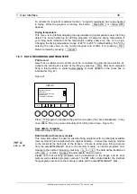
Figure 22 


Please refer to Fig. 22 to connect a memory module to the rear of the housing. 
Disconnect a memory module by softly pressing the two clamps at the narrow sides of 
the module. Then pull it off from the plug-in connection. 
 

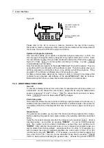
Update set programs (optional) 

This menu item allows you to update set programs (program memories 1 to 100). It is 
the only way to change the memory assignment in program memories 1 to 100.  Insert 
the new software module in the provided socket at the back side of the furnace (see Fig 
Figure 21). Press   O.K.   to run the update  and then go to 

Setup, 

 or press    Cancel    

to automatically return to 

Setup

Note, that all old set programs of the 

AUSTROMAT D4

 will be erased.  They are 

overwritten with the set programs of the software module.  Therefore, please save your 
old firing programs by writing them down, or by printing out all firing programs.  Firing 
programs 101 to 200 are not affected when this menu item is used. 
A software module (same design as the memory module) is included in the delivery that 
contains the set programs and software of the 

AUSTROMAT D4

 as backups. 

Before starting the furnace, remove this module and place it in a safe location. 


:::::::


memory module with


two clamps

connection socket at


back side of the 
furnace 

7.6.4 ADDITIONAL 

FUNCTIONS 

Oven ID 

To prevent confusing furnaces from each other (for example when printing records), an 
individual ID  can be entered for each furnace . Assign the ID using the alphanumeric 
keypad, or pressing 

"+"

 and 

"-"

. Press     O.K.   to accept the ID and return to Setup.  

Press     Cancel   to return to Setup without saving changes. 
 

Print all programs 

This setup item allows the user to print out all firing programs stored in the furnace on a 
suitable printer (see Section 8). Make sure that there is sufficient paper in the printer for 
a complete printout. Run this program from time to time to have a paper record of your 
data.  

 
General code 

The general code enables you to protect the furnace and firing programs from change.  
Before activating the general code, please observe the operating restrictions described 
below. 
Select the menu item General code from the 

Setup

 menu by pressing    O.K.  .   Enter a 

four-digit number, and confirm by pressing 

"ENTER"

.  In order to avoid accidental 

entry, this number must be entered identically a second time and confirmed with 

"ENTER

".  After entering the general code, you can choose what program range you 

wish to protect from change (default:   all programs from 1 to 200).  If, for example, you 
wish to protect the range of individual programs, the correct entry is from 101 to 200 
(confirm each entry with 

"ENTER"

).  If, for example, you wish to protect program 150 

only, enter 150 to 150.  The entry can be cancelled at any time by pressing    Cancel     
(return to 

Setup

 without activating the general code).  Activate the general code with  

DEKEMA Dental-Keramiköfen GmbH, AUSTROMAT

®

 D4, Version 3, 2006


Summary of Contents for Austromat D4

Page 1: ...OPERATING INSTRUCTIONS A U S T R O M A T D 4 Version 3 DEKEMA Dental Keramiköfen GmbH Industriestrasse 22 D 83395 Freilassing Phone 49 0 86 54 46 390 Fax 49 0 86 54 66 195 www dekema com info dekema com ...

Page 2: ...16 7 1 FIRST STEPS 16 7 1 1 CONTROLS 17 7 1 2 SET PROGRAMS OPTIONAL 19 7 1 3 INDIVIDUAL FIRING PROGRAMS 21 7 2 PROGRAM MANAGER 23 7 3 PROGRAM DISPLAY 24 7 4 PROGRAM PROCEDURE 26 7 5 PROGRAM EDITOR 29 7 5 1 INDIVIDUAL PROGRAMS STANDARD 30 7 5 2 INDIVIDUAL PROGRAMS PROFESSIONAL 31 7 5 3 INDIVIDUAL PROGRAMS PRESS PROGRAMS ONLY D4PRESS 31 7 5 4 SET PROGRAMS 32 7 5 5 EDITING WHILE THE PROGRAM IS RUNNIN...

Page 3: ...is to assist you in troubleshooting References in the text refer to this section Finally the index enables you to quickly find specific functions or commands Please note the following warning symbols This symbol warns of hazardous electrical voltage where there is a danger to life and limb Note these instructions on the device and be especially careful This symbol indicates a burning hazard from h...

Page 4: ...y module same construction Max firing temperature 1 200 C Max rate of temperature rise 160 C min from 20 C to 500 C 120 C min from 500 C to 1000 C 60 C min from 1 000 C to 1 200 C Dimensions 35 x 63 x 28 cm W x H x D D4 35 x 74 x 28 cm W x H x D D4press Weight 18 0 kg D4 18 5 kg D4press 2 2 VACUUM PUMP UNIT Pump type Service free diaphragm pump Supply voltage depending on the type pump rating plat...

Page 5: ...ith sealing ring yellow O ring and the firing table on which the objects to be fired are placed On the cover plate there is a cylindrical height gauge that corresponds with the free height of the firing chamber On the front of the bottom part of the furnace you will find the following controls screen function keys softkeys alphanumeric keypad control keys and an LED to display when the device is r...

Page 6: ...llowing connections exist one plug connection with two clips to hold the soft or memory module a serial interface for a PC connection top socket connector the socket connector for the vacuum pump power cable and a connection for the vacuum line top section of furnace with firing chamber back column bottom section of furnace with electronic and mechanical components mains cable connection vacuum pu...

Page 7: ...hat nothing extends over the edge of the firing table The object to be fired and the heat insulation material may otherwise be damaged when you close the furnace Only use fuses with the indicated lag and nominal current see p 4 Tecnical Specifications Acute danger of burning only the D4press If the lift is moved down after running a press program visually check if the press muffle is on the firing...

Page 8: ...ructions in Section 4 2 Note that the furnace requires several hours to cool after it is turned off Do not run the connection lines past hot locations of the furnace and especially avoid direct contact 4 2 SETUP Set up the furnace in a suitable place on a dry flat solid surface Make sure that flammable materials or objects that can be damaged by heat are sufficiently distance from the furnace Neve...

Page 9: ...his can cause injury from burns or electrical shock The firing chamber has a clear height of 36 mm The fired objects including the firing tray may not exceed this height since the temperature sensor could otherwise be damaged On the cover plate there is a cylindrical height gauge that corresponds with the free height of the firing chamber Figure 3 Height gauge 36 mm max height In the Press mode of...

Page 10: ...hey should only be performed by authorized professionals After repair work the furnace must undergo a safety check Federal Republic of Germany VDE 0701 International according to the respective national guidelines DEKEMA Dental Keramiköfen GmbH AUSTROMAT D4 Version 3 2006 ...

Page 11: ... making sure that the guide groove is aligned Screw tight the cable in the socket since a bad electrical contact can damage the furnace Step 5 Connect the pump vacuum line silicon tube to the vacuum connector on the back of the furnace Step 6 Turn on the furnace The furnace performs an internal software and hardware check and the lift moves down automatically If necessary remove any ceramic dust f...

Page 12: ...alibration is carried out by means of the calibration factor CCF Observe the following instructions TIP F see p 43 For new furnaces we recommend that you calibrate the temperature for the first time after approximately six months An internal monitoring program notifies you when you should calibrate the furnace temperature TIP C see p 42 Make sure that the heating element and thermocouple are not d...

Page 13: ...ature o k effective temperature slightly too high lower CCF value c 3 points effective temperature too high lower CCF value c 5 points 6 3 CHECK PROGRAM The AUSTROMAT D4 has an internal program that checks the function of the major components check program Regularly using this non editable program makes it easier for you and the responsible service personnel to identify aged components such as hea...

Page 14: ...at lasts approximately three years After a maximum of three years the battery should be replaced for the memory modules to work properly and to avoid loss of your firing programs When turned on the furnace indicates the battery charge Figure 7 100 means the battery is new and approximately 10 means that the battery is an average of 2 years old Note that this value is reached much earlier when the ...

Page 15: ...uipment by your service partner This will ensure superior firing results If you need to replace wearing parts or want to update the set programs please consult the responsible service partner If more extensive repairs to the furnace or pump are required please also contact your service partner Please direct any questions for the manufacturer to the following address DEKEMA Dental Keramiköfen GmbH ...

Page 16: ...of the device Figure 5 Operating diagram After the oven is turned on you are initially shown information on the device software and device settings Then you automatically go to Program Manager menu Here you can select firing programs and administer the memories i e delete or copy firing programs he most important menu for the user the Program Display is accessed from the Program Manager This shows...

Page 17: ...s and menu items are in italics Figure 6 AUSTROMAT D4 operating elements The screen display is divided into two areas see Fig 6 the actual display area and the bar with the functions of the function keys on the bottom of the screen function bar Select or confirm the menu items offered in the display field by pressing the associated function key The alphanumeric keys to the right of the screen are ...

Page 18: ... 001 100 can be reserved for set programs or can be freely assigned depending on the version The other 100 program number 101 200 are available for individual firing programs In order to distinguish between the programs the program number and name and program entries are displayed in different font colors on screen when the set programs are preset The program with number 001 PREHEATING PROGRAM has...

Page 19: ... and the selection options in the function bar Fig 9 Figure 9 The following are displayed in the top line from left the temperature Tc of the firing chamber an empty field for vacuum display during program processing the 9 digit firing number 123456789 and the expected duration of the firing program in hours minutes seconds 00 12 22 In day to day use the Tc display will initially flash This means ...

Page 20: ...by a square marker The values of the the diagram e g Drying 04 00 min holding time With Å and Æ you can move the marker along the program time line and browse through the individual steps Use Program Display to return to text display mode In this way you can switch between text and graphic display You can start the firing program by pressing Program Start both in text mode and graphic mode If the ...

Page 21: ...of 011 Now press Change name if you only want to enter a group name without creating a related program The window for entering a name appears on the screen Enter for example the name NEW_PROCEDURE_2005 _ stands for a space on the alphanumeric keypad The alphanumeric keys have four to five characters in the name entry mode and only in this mode The first character is the left one in the smaller fon...

Page 22: ...ure 80 temperature rise rate 1 min firing temperature holding time no holding time for cooling and relaxation and 100 VAC level If you confirm an incorrect entry by pressing ENTER you can correct the entry by moving the cursor to the position by pressing Å or Æ and entering the correct value Please note that an input value is only accepted by confirming with ENTER an input is outside the permissib...

Page 23: ...grams Section 7 1 2 depending on software version and M MANAGER The Program Manager is used to select a firing program memories copying deleting firing programs Altogether the offers 200 memory slo are reserved for set p memories 101 200 are reserved for individual programs Section 7 1 3 In the set programs the firing procedure is pre defined and only certain parameters may be modified Specificall...

Page 24: ...ividual program The target on the other hand must be a program number from the individual range If the target is already occupied you will be asked whether you want to overwrite the target A program cannot be copied onto itself An empty program cannot be copied Two programs may not have the same name During copying the source and target are thus automatically numbered Fig 16 programs 101 102 Delet...

Page 25: ...The furnace is evacuated after expiration of the Preheating program step Please note that the vacuum holding time is included in the holding time e g for temperature 1 An empty entry box in column 2 3 4 means that the respective value is automatically specified by the program step or is not required The function bar displays the menu options empty field no function The following options are availa...

Page 26: ...g options function bar ProgramManager Opens the Program Manager menu Setup Opens the Setup menu 7 4 PROGRAM PROCEDURE A firing program is started from the Program Display by pressing Program Start TIP E 3 TIP A 2 see p 4 see p 4 This can also be done from the graphic display of the program procedure The program steps are processed according to the set sequence of the entry mask Standard or Profess...

Page 27: ... Wash firing Drying 4 00 Closing 2 00 Preheating 550 C Temperature 1 980 C 80 C min 1 00 Temperature 2 C C min Temperature 3 C C min VAC off level hold 980 C 100 firing chamber temperature vacuum level firing number remianing firing duraction 1 4 00 min drying 2 Closing 2 00 min 3 Set preheating temperature no ho 4 Evacuate to 100 5 Set temperature 1 wi 6 Vent 7 1 00 min 8 End of program the lift ...

Page 28: ...AC hold can only be entered if the temperature VAC off coincides with the temperatures 1 2 3 and if a holding time has also been entered at this temperature The vacuum holding time does not count as an additional holding time Temperature 2 3 is set at the respective heat up rate starting from temperature 1 2 In the STANDARD entry mask temperature 1 is called FIRING TEMPERATURE Temperature 2 is pre...

Page 29: ...ck to the last program by default or o back to the start window after a power failure or rebooting 7 5 PROGRAM EDITOR The Program Editor is used to create new firing programs or to edit existing programs Furthermore it is possible to edit a firing program in progress The Program Editor menu is activated from the Program Display menu by selecting Program Edit The options differ slightly depending o...

Page 30: ...ring temperature 3 relaxation temperature predefined as 65 of firing temperature 4 cooling relaxation temperature is activated as quickly as possible opening of firing chamber 5 venting vacuum off when firing temperature is reached 6 0 pump off 100 continuous pump operation The permissible values for VAC level are divided in steps of ten from 0 to 100 The function bar in the Program Editor Fig 19 ...

Page 31: ...emperature rise C min Holding period min sec Dry 0 00 9 59 Close 0 00 9 59 Preheat 100 700 0 00 9 59 Temperature 1 1 100 1200 2 99 MAX 4 0 00 99 59 Temperature 2 2 100 1200 2 99 MAX 4 0 00 99 59 Temperature 3 3 100 1200 2 99 MAX 4 0 00 99 59 Vacuum Tmax 5 level in 6 0 00 99 59 1 Temperature 1 Firing temperature in Standard entry mask 2 Temperature 2 Cooling temperature in Standard entry mask 3 Tem...

Page 32: ...he Program Editor If you do not press a key in this menu within 20 seconds you will automatically return to Program Procedure The editing options are the same as the options in Sections 7 5 2 and 7 5 3 However only the values of unprocessed program steps may be edited Only between these steps and values can the position be changed with Å and Æ ENTER confirms an individual value and stores it in th...

Page 33: ... Select a menu item The selected function is displayed on a light background Cancel Exit the Setup menu and return to the previous menu e g Program Display Please note the restricted options of the Setup menu when the general code is activated Section 7 6 4 7 6 1 FURNACE SETTINGS Set display contrast A contrast test picture is displayed on the screen The function bar offers the following options O...

Page 34: ...sh by pressing The active language setting is displayed on a light background Press O K to accept the changes and return to Setup Press Cancel to return to Setup without saving changes C F switchover Select the desired temperature display C F The active temperature setting is displayed on a light background Press O K to accept the changes and return to Setup Press Cancel to return to Setup without...

Page 35: ... furnace indicates any malfunctions and displays a warning if it is likely that a firing process will not be correctly completed Performing the check program regularly also makes it easier to identify a worn heating element and to diagnose any faults in the vacuum system The structure and interpretation of the diagnosis data are important for the service personnel see the Diagnosis data menu item ...

Page 36: ...ndicate this Fig 21 Figure 21 Press O K again to deactivate the print record option the check disappears In any O K Cancel SETUP Set display contrast Print record Computer data recording General code Temperature calibration case after a firing run you can manually print a firing record see Figure 16 Save data to computer Data recording is not active Data transfer with memory module This menu item ...

Page 37: ...from each other for example when printing records an individual ID can be entered for each furnace Assign the ID using the alphanumeric keypad or pressing and Press O K to accept the ID and return to Setup Press Cancel to return to Setup without saving changes Print all programs This setup item allows the user to print out all firing programs stored in the furnace on a suitable printer see Section...

Page 38: ...ace has not been used for a the program number Editor cannot be invoked for these programs copying Program Manager Setup General code Check program Diagnostic data Leak test Print all pr activated you must first deactivate the code In order to deactivate the general code select this menu item in Setup and enter the correct code confirm with ENTER S The screen sav while and thereby protects the dis...

Page 39: ...et connector to connect to the furnace The data is printed out in standard printing characters ASCII Connection Turn off the furnace ON OFF switch is on the rear see p 6 Make sure that the printer is turned off Connect the furnace and printer with the interface cable Turn on both devices There are two options for printing the records 1 Manual printout After the program is finished press the functi...

Page 40: ...nace data Oven ID 00 Software version AUSTROMAT D4 V 01 20 Last check program 14 07 99 Temperature calibration 1 010 Firing program Program number 102 Program name DENTIN 1 Program procedure Dry 3 00 Close 3 00 Preheat 550 2 00 Firing temperature 920 55 1 00 Cool Relax VAC level 100 Starting the program 16 24 56 Air pressure 961 Total firing time 00 17 10 Firing processed correctly DEKEMA Dental K...

Page 41: ...ministering and archiving firing programs Interactive creation and editing of firing programs Transfer of firing programs Reading out and archiving QM reports Converting firing programs In addition DREAM allows you to directly access our comprehensive firing program database on the Internet DREAM can be downloaded free of charge from the download area of our internet site www dekema com DEKEMA Den...

Page 42: ...pection Look into the open firing chamber from below while the furnace is switched off and cold The heating coil must be evenly inserted in the glass tube and evenly distributed on the support tube at the core guided heating element If the heating coil is deformed or if the glass is broken the heating element should be replaced C Thermoelement temperature calibration Visually inspect the thermoele...

Page 43: ...ials are subjected to less radiated heat than corresponds to the cooling temperature To offset this effect the lift moves up slightly closer to the hot chamber When the firing chamber has reached cooling temperature the lift should be completely at the top and the firing chamber should be closed again This ensures that the fired materials are always approximately subjected to cooling temperature d...

Page 44: ... 6 Diagnosis file 13 Diagnostic data 35 DREAM 39 41 43 Drying 27 43 Drying temperature 36 Evacuation 28 Firing number 19 27 Firing parameters 43 Firing program See program Firing temperature See temperature firing Firing tray 43 Flooding See Venting Function key 17 Furnace ID 37 Fuses 6 General code 37 Deactivate 38 Heading without program 21 Heating element 42 Height gauge 5 ID 37 Installation as...

Page 45: ...ervice functions 38 Silver wire 13 Sleep mode 29 36 Sleep Modus 36 Software module 37 Startup 11 Switching off 42 Technical specifications Ceramic furnace 4 Vacuum pump 4 Temperatur 1 2 3 27 Temperature Cooling 30 Firing 30 Relaxation 30 Temperature calibration 12 35 42 Temperature display 19 Temperature display C F 34 Temperature rise 4 Test firing 43 Thermoelement 42 Time 34 Transport 15 Ultimat...

Reviews: