DEKKER Vacuum Technologies, Inc. – HullVac / September 2016
10
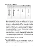
Cooling Capacities and Port Sizes
Pump
Pump CFM
HP
Cooling Water
Capacities
(gpm)
Cooling Water
Port Sizes (Inch
– NPT)
HV55A
52
3
-
-
HV140A
130
5
-
-
HV160
150
7.5
1.5
1/2
HV412XT
300/340
10/15
2.5
1/2
HV450
450
20
3.5
3/4
HV635
635
30
5
3/4
HV850
850
40
7
1
HVC35A
32
3
-
-
HVC65
65
5
1
1/2
HVC100A
95
5
-
-
HVC180
180
10
2
1/2
HVC340
340
20
2.5
1/2
Electrical Preparation
All system wiring is performed at the factory if a control panel is supplied and mounted on skid. Check area
classification to ensure all electrical enclosures comply with code. Required customer wiring is minimal, but
should be done by a qualified electrician in compliance with OSHA, National Electric Code and all applicable
federal, state, and local codes concerning switches, fused disconnects, etc. DEKKER includes a wiring
diagram in the control panel for use by the installer. DEKKER recommends a main disconnect switch be
fitted between the vacuum system and the incoming power. Wire the motor using appropriate starters and
fuses to comply with local electrical codes.
All
HullVac
pumps are equipped with an oil flow solenoid valve that prevents oil from entering the
pumping chamber when the pump is not in use. Oil flow solenoid coil voltage should match the motor
voltage. The solenoid valve coil is energized whenever the motor is energized. During initial operation,
confirm valve operation by holding a screwdriver or other metal object close to, but not touching the valve
stem top. If the coil is energized, a gentle tugging or vibration will be detected. An oil stream will also be
present on the oil level site port whenever the pump is in operation. If an oil stream or splash is not
present, check the solenoid valve for proper operation.
After the electrical wiring connections are completed, check the incoming voltage to make sure the
incoming voltage is the same as the vacuum system voltage. Line voltage should be within the voltage
tolerance as specified on the motor. Check the system for proper motor rotation. The direction of rotation
is always counterclockwise when looking at the driven end and is marked by an arrow on the motor or
pump housing. Jog the motor by pressing the ON button and then the OFF button. If the rotation is
incorrect switch any two of the three main power leads on the contactor inside the control panel. Failure
to do so could result in serious equipment damage.
WARNING: Install, ground, and maintain equipment in accordance with the OSHA, National
Electrical Code and all applicable federal, state, and local codes.
Pipe Connections and Sizing
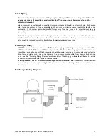
Before installation, remove all protective inserts on the pump suction and discharge. Piping connected to
the system must be installed without imposing any strain on the system components. Improperly installed
piping can result in misalignment, general operating problems, and pump failure. Use flexible connectors and
vibration isolators where necessary. Piping must be cleaned of debris before installation.

