background image

DEKKER Vacuum Technologies, Inc. – HullVac / September 2016 

25 

OPTIONAL ACCESSORIES 

The following accessories are available for 

HullVac 

rotary piston vacuum pump systems. 


Automatic Inlet Vent Valve:

 Includes a normally open solenoid valve and filter assembly mounted 

to the pump inlet port. When power is shut off, the pump inlet and manifold will be vented to 
atmosphere. This will prevent accidental oil suckback into the manifold and process chamber and will 
also vent the chamber up to atmosphere.  


Automatic Inlet Isolation Valve:

 Consists of a pneumatically actuated ball valve mounted on the 

pump inlet that automatically closes whenever power is shut off. 

Note: This includes the 

automatic inlet vent valve. 


Temperature Control Valve:

 Reduces cooling water flow by up to 90% while it controls pump 

operating temperature within the optimal range of 140-165°F. This temperature optimizes water and 
solvent evaporation from the oil supply while preventing damage due to excessive heating. 


Inlet Filter:

 Traps particulate larger than the internal clearances of the pump (5 micron). Must be 

installed horizontally. 


Oil Mist Eliminators:

 Strips atomized oil droplets from the exhaust stream, reducing the 

appearance of smoke. Assembly comes complete with a ball valve on the canister drain and a 0 to 15 
psig gauge to monitor filter element condition. 
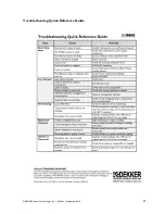
 

TROUBLESHOOTING 

The  following  is  a  basic  troubleshooting  guide.  Please  consult  the  factory  for  advanced  troubleshooting. 
Each 

HullVac


system is tested and checked at the factory. Always indicate system model and serial number 

when calling. 

WARNING:  Before  attempting  any  repairs,  disconnect  all  power  from  the  system  by 

switching off the main breaker or disconnect switch. All electrical work should be done by a 
qualified  electrician  in  compliance  with  OSHA,  National  Electric  Code  and  any  other 
applicable local electrical code. 


Start-Stop Problems 

System will not start in HAND or AUTO position:


1.


No main AC power. Confirm that the main AC power disconnect is ON and supplying power to the control 

panel. This can be measured with an AC voltmeter at the power supply terminals in the control panel. Refer to 
the electrical control panel diagram supplied with the system. If main AC power is not present at the power 

supply, verify incoming AC voltage on the motor contactor. 

2.


Check if the disconnects or circuit breaker is switched on. 

3.


Check the overload setting on the starter. 

4.


Check all fuses. 

5.


Ensure that the proper voltage is supplied and that the wire size is correct. 

6.


Check electrical control panel (if installed) and make sure that all of the wires are tight. Wires may vibrate 

loose during shipment or operation. 

7.


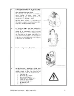
Check oil level. Add oil to reservoir if needed. 

8.


Check if the pump has seized by removing the belt guard and rotating the belts by hand (

disconnect 

power first

). If a rubbing noise or binding is observed, contact the factory.


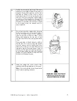
System shuts down while running: 

1.


Check oil temperature. Normal system operating temperature is between 140-160°F as measured on the oil 
solenoid valve body located below the exhaust port. 

2.


Ensure that the proper voltage is supplied and that the wire size is correct. 

3.


Check for loose electrical connections. 
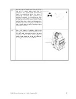
4.


Check if the pump has seized by removing the belt guard and rotating the belts by hand (

disconnect 

power first

). If a rubbing noise or binding is observed, contact the factory.  

Summary of Contents for HullVac HV140A

Page 1: ...Installation Operation Maintenance Manual Rotary Piston Vacuum Pumps Systems SERIAL NO ___________________________ September 2016 ...

Page 2: ... CAPACITIES AND PORT SIZES 10 ELECTRICAL PREPARATION 10 PIPE CONNECTIONS AND SIZING 10 INLET PIPING 11 DISCHARGE PIPING 11 COOLING WATER PIPING WATER COOLED SYSTEMS ONLY 12 ELECTRICAL CONTROLS IF INCLUDED 12 START UP PROCEDURES 13 BELT TENSION FOR V BELT DRIVES 15 SHUT DOWN PROCEDURE 19 MAINTENANCE SCHEDULE 20 DURING FIRST MONTH OF OPERATION 20 EVERY DAY 20 EVERY 3 MONTHS 20 EVERY YEAR 20 EVERY 5 ...

Page 3: ... REQUIRED 23 MOTOR BEARING LUBRICATION SCHEDULE 24 OPTIONAL ACCESSORIES 25 TROUBLESHOOTING 25 START STOP PROBLEMS 25 VACUUM PROBLEMS 26 OVERHEATING PROBLEMS 26 NOISE AND VIBRATION PROBLEMS 26 OIL PROBLEMS 26 TROUBLESHOOTING QUICK REFERENCE GUIDE 27 WARRANTY REPLACEMENT RETURN POLICIES 28 ...

Page 4: ...uum Technologies Inc HullVac September 2016 4 THIS INSTALLATION OPERATION AND MAINTENANCE MANUAL MUST STAY WITH EQUIPMENT PLEASE REGISTER YOUR EQUIPMENT WARRANTY AND START UP RECORD ONLINE AT WWW DEKKERVACUUM COM ...

Page 5: ...parts or system information always have the pump or system model number and serial number s ready Refer to the bill of lading or the gold colored system information plate attached to the system see image below Gold colored system information plate Parts should be purchased from the nearest authorized DEKKER Vacuum Technologies Inc hereafter referred to as DEKKER representative visit www dekkervacu...

Page 6: ...ersonal injury Please review and follow all instructions in this manual before attempting to install start or operate the equipment SAFETY All vacuum pumps systems and or compressors hereafter referred to as the Product offered by DEKKER have been designed and manufactured for safe operation However the responsibility for safe operation rests with those who use and maintain these products The safe...

Page 7: ...film of oil between the piston and the cylinder Once the piston makes a complete cycle the clearance volume is completely filled with oil increasing the compression ratios within the pump This design is what gives rotary piston pumps their deep vacuum levels and durability Depending on the application and desired vacuum level HullVac pumps are offered in single stage or two stage configurations Th...

Page 8: ...l All wires should be terminated and connections tight Control panel components should be tight on DIN rail or other mounts fasteners Are there any leaks or puddles around the pump Specify hose piping or housing leak System must be given an initial startup test as soon as possible after delivery This is to ensure that the motor has not shifted out of alignment during transit as well as to verify t...

Page 9: ...s therefore important to install the unit in a reasonably cool area where the temperature does not exceed 104 F For higher ambient temperatures contact the factory For water cooled vacuum systems it is necessary to check cooling water supply A proper consistent water flow must be maintained for adequate cooling Refer to the Cooling Capacities and Port Sizes table on page 10 for recommended cooling...

Page 10: ...e operation by holding a screwdriver or other metal object close to but not touching the valve stem top If the coil is energized a gentle tugging or vibration will be detected An oil stream will also be present on the oil level site port whenever the pump is in operation If an oil stream or splash is not present check the solenoid valve for proper operation After the electrical wiring connections ...

Page 11: ...uld be installed at the inlet port For more information consult your dealer or factory A vacuum rated isolation valve should be installed for routine blank off performance testing and servicing Discharge Piping DEKKER recommends as a minimum CPVC discharge piping as discharge temps may exceed 170 F CPVC is rated for 200 F max and PVC is only rated for 140 F max Discharge piping must be at least th...

Page 12: ...ED Disconnect Handles Disconnect handles must be turned on to energize the system The handles must be turned off to open control panel CAUTION High voltage main disconnect must be off when servicing panel HOA Hand Off Auto Selector Switch Pump units will start in HAND mode unless units are in a shutdown alarm condition The pumps will bypass vacuum setpoints AUTO mode allows units to start based on...

Page 13: ...ers are removed from system and tagging information is followed for successful startup 2 Remove the belt guard and rotate the pump two complete revolutions by hand in the counterclockwise direction This will clear accumulated oil from the pump housing that can collect during long inactive periods Reinstall the belt guard ...

Page 14: ... belt when slipping Never apply belt dressing as this will damage the belt and cause early failure Simple Tensioning Procedure 1 Measure the span length 2 At the center of the span apply a force perpendicular to the span large enough to deflect the belt 1 64 inch for every inch of span length For example one deflection of a 100 inch span would be 100 64 or 1 9 16 inches 3 Compare the force you hav...

Page 15: ... 4 3 4 5 5 0 1200 1800 5 0 4 1 4 6 4 8 5 6 1200 1800 6 0 4 8 5 3 5 5 6 3 1200 1800 8 0 5 7 6 2 6 4 7 2 AX 1800 3600 3 0 2 5 2 8 3 0 3 3 1800 3600 4 0 3 3 3 6 3 8 4 2 1800 3600 5 0 3 7 4 1 4 3 4 6 1800 3600 7 0 4 3 4 6 4 8 5 3 BX 1200 1800 4 6 5 2 5 8 6 0 6 9 1200 1800 5 0 5 4 6 0 6 3 7 1 1200 1800 6 0 6 0 6 4 6 7 7 7 1200 1800 8 0 6 6 7 1 7 5 8 2 Tensioning Table and installation image courtesy of...

Page 16: ... rotation The correct direction of rotation is marked by an arrow on the motor or pump housing If direction is incorrect switch any two of the three leads at the power connection The correct direction of rotation is counterclockwise facing the pump from the drive end and clockwise if viewed from the non drive end 6 Turn the cooling water on if applicable 7 Energize the motor a slight belt slipping...

Page 17: ... minutes Proper oil fill is confirmed when the site port oil level is at least level During initial evacuation the site port oil level may rise but will fall as the pump operates below 1 torr During operation oil should always be visible in the site port If it is not stop the pump and add oil to the reservoir until it is visible around two thirds up the oil site port An exact fill level is not req...

Page 18: ...nning for a few minutes or until warmed up the pump should reach an ultimate pressure of 50 microns of mercury or less on a thermocouple or equivalent type of vacuum gauge If a Bourdon type of vacuum gauge is used it should read close to 30 inches of vacuum 12 After 15 30 minutes of operation check pump operating temperature which should be in the 140 160 F range at the solenoid body The casing te...

Page 19: ... gas ballast valves to vent the pump to atmosphere If system is equipped with an automatic vent valve or an anti suckback valve no action is needed Failure to vent the pump to atmosphere may cause oil to fill into the pumping chamber and travel back through the inlet manifold into the vacuum process chamber 4 If water cooled turn off the cooling water supply ...

Page 20: ...o 45 foot pounds Every Day Check oil level daily oil level should be between 1 2 and 2 3 level in the site port while in operation Check pump temperature daily casing temperature should not exceed 180 F Every 3 Months Check belt tension Verify tightness of pump mounting bolts Every Year Remove the oil reservoir access plate Clean and inspect the sump for signs of metal filings that may be an indic...

Page 21: ...er it appears white or yellow foams consistently or when dirty Oil change frequency depends on the materials being pumped For clean operation oil should be changed every 3000 operating hours or every 9 months whichever comes first For other operation oil change could range from once or twice a week or less dependent upon the type of application The most common contamination is water in the oil and...

Page 22: ...tions then open the drain valve again to scavenge residual oil This will force residual oil from the pumping chamber into the oil reservoir where it can be drained Follow these steps to fill with new oil Close the oil drain valve and fill the reservoir to the 2 3 site port level by pouring oil through the oil fill port located on top of the pump Reconnect main power to pump Close the inlet isolati...

Page 23: ...y temperature does not exceed 180 F as measured on the casting surface below the sight port Oil Solenoid Valve The oil solenoid valve located under the exhaust port prevents oil from filling into the pumping chamber when the pump is turned off or when there is a power failure It is critical that this valve operates properly If the valve malfunctions in an open position oil will flow back into the ...

Page 24: ... lubricants be sure to grease and then re grease after 100 hours of service Frequency volume of greasing is based on service conditions speed and frame size See the Motor Bearing Lubrication Schedule table below Standard conditions 8 hour day operation normal or light loading clean environment at a 100ºF maximum ambient temperature Severe conditions 24 hour operation or shock loading vibration dir...

Page 25: ...Before attempting any repairs disconnect all power from the system by switching off the main breaker or disconnect switch All electrical work should be done by a qualified electrician in compliance with OSHA National Electric Code and any other applicable local electrical code Start Stop Problems System will not start in HAND or AUTO position 1 No main AC power Confirm that the main AC power disco...

Page 26: ...ambient air temperature is 104 F or below Unit overheats on start up in low ambient temperatures 1 Stop system and disconnect power 2 Verify oil temperature Oil tends to thicken in temperatures of 55 F and below Noise and Vibration Problems The system is making an abnormal noise or sound 1 Stop system and disconnect power 2 Check belt tension and alignment 3 Ensure that the oil level is correct 4 ...

Page 27: ...DEKKER Vacuum Technologies Inc HullVac September 2016 27 Troubleshooting Quick Reference Guide ...

Page 28: ...lects to use a non DEKKER seal fluid which has NOT been approved by DEKKER product warranty may be void 3 Year Warranty Vmax systems 3 year warranty with DEKKER Vmaxol seal fluid 2 year warranty with non DEKKER seal fluid HullVac pumps and systems 3 year warranty with DEKKER HullVac seal fluid 2 year warranty with non DEKKER seal fluid 2 Year Warranty DuraVane pumps systems and compressors 2 year ...

Page 29: ... the DEKKER s written consent In lieu of the foregoing remedy DEKKER may if DEKKER so elects redesign and or replace the product or refund the full purchase price thereof If purchaser disassembles the product for any reason without the written consent of DEKKER this warranty shall be void Limitation of liability for DEKKER vacuum pumps systems and compressors DEKKER s obligations are limited to re...

Page 30: ...duct pre paid Collect freight or parcels will be refused unless prior approval is given by After Sales Associate A minimum 15 restock fee applies If product is damaged by customer as a result of mishandling or poor packaging for return shipment this fee may be increased as determined by DEKKER Return for Replacement incorrect part number received due to DEKKER shipping error New purchase order is ...

Reviews: