
DEKKER Vacuum Technologies, Inc. – HullVac / September 2016
26
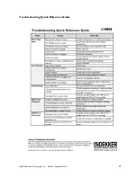
Vacuum Problems
System operates, but does not achieve desired vacuum level:
1.
Stop system and disconnect power.
2.
Check if the inlet valve is open and inlet filter (if equipped with filter) is clean.
3.
Ensure that no lines are open to the atmosphere, causing loss of vacuum.
4.
Check for leaks in piping systems, using conventional leak detection methods.
5.
Ensure that the oil level is correct.
6.
Check if the oil solenoid valve is working.
7.
Check if the motor rotation is correct. The correct direction of rotation is counterclockwise facing
the pump from the drive end and clockwise if viewed from the non-drive end. If incorrect, switch any
two of the three main power leads.
Overheating Problems
System overheats or operates above 180
o
F:
1.
Stop system and disconnect power.
2.
Check if the oil solenoid valve is working.
3.
Ensure that the oil level is correct.
4.
Verify cooling water flow, if applicable.
5.
Verify ambient air temperature is 104°F or below.
Unit overheats on start-up in low ambient temperatures:
1.
Stop system and disconnect power.
2.
Verify oil temperature. Oil tends to thicken in temperatures of 55°F and below.
Noise and Vibration Problems
The system is making an abnormal noise or sound:
1.
Stop system and disconnect power.
2.
Check belt tension and alignment.
3.
Ensure that the oil level is correct.
4.
Check the inlet filter (if equipped with filter) and clean if necessary.
5.
Check if the inlet valve is closed.
System is vibrating excessively:
1.
Stop system and disconnect power.
2.
Check belt tension and alignment.
3.
Check if baseplate is properly supported. Uneven floor will distort baseplate, which could cause
vibrating problems.
4.
Check that the mounting bolts of pump are not loose. Tighten as required.
Oil Problems
System uses excessive oil or produces an oil-mist:
1.
Ensure that the pump is pulling a deep vacuum level (deeper than 100 torr for single-stage and 10 torr
for two-stage).
2.
Stop system and disconnect power.
3.
Confirm oil level is not too high.
4.
Confirm that pump is using factory recommended oil.
5.
Ensure that discharge piping is arranged correctly.


