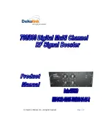
background image


© Dekolink Wireless Ltd.—All Rights Reserved 


 Rev. 1.3 


Summary of Contents for Deko4078SD

Page 1: ... Dekolink Wireless Ltd All Rights Reserved Rev 1 3 ...

Page 2: ...l herein is proprietary to Dekolink Wireless Ltd Any unauthorized reproduction use or disclosure of any part thereof is strictly prohibited All trademarks and registered trademarks are the property of their respective owners DISCLAIMER OF LIABILITY The remedies provided herein are the Buyer s sole and exclusive remedies Dekolink Wireless Ltd shall not be viable for any direct incidental or consequ...

Page 3: ...should carry out adjustment maintenance or repairs to the components of this equipment DANGER ELECTRICAL SHOCK This equipment is intended to be installed indoor Wet conditions increase the potential for receiving an electric shock when installing or using electrically powered equipment To prevent electrical shock when installing or modifying the system power wiring disconnect the wiring at the pow...

Page 4: ...DF Dekolink Digital Filter DL Downlink The path covered from the Base Transceiver Station BTS to the subscribers service area via the 700 800 DMSB UHF DSP Digital Signal Processing ESD Electro Static Discharge FPGA Field Programmable Gate Array IF Intermediate Frequency PLL Phased Locked Loop RF Radio Frequency MT 700 800 DMSB signal booster Management Tool UL Uplink The path covered from the subs...

Page 5: ...D P N 300SC30031 Rev 1 2 Proprietary Data Page 5 REVISION HISTORY The revision history for this document is shown in Table 1 1 Table 1 1 Revision history P N Revision Date Description 300SC30031 1 0 14 July 2008 Initial Version 300SC30031 1 2 11 AUG 08 Modifying model numbers ...

Page 6: ...nd Installation Requirements 16 2 1 Rack Installation Environment and Cables 16 2 2 Antenna Requirements 16 2 2 1 Base Donor Antenna 16 2 2 2 Mobile Service Antenna 16 2 3 Grounding Wires Requirements 17 2 4 RF Cable Installation Guidelines 17 3 Physical Installation 18 3 1 Overview 18 3 2 Unpacking 18 3 3 Connecting the Donor and Service Antennas 19 3 4 Verifying Ground Connections 20 3 5 Power U...

Page 7: ...3 Deleting Filters 42 6 2 Generating ID Tone on Channels 42 6 3 Modifying DMSB Booster Parameters 44 6 4 Viewing Online Booster Parameters 44 6 5 Monitoring Alarms 45 6 5 1 System Alarms and External Alarms 45 6 5 2 Specific Channel Alarms 47 6 6 Viewing Graphic Display of Filter 48 6 7 Defining the External Alarms 48 6 8 Sliding Window Configuration 50 6 9 Viewing System Information 50 7 Administ...

Page 8: ...g the Booster Parameters 63 Configuring the Channels 64 Navigating the Signal Booster Management Tool 66 Access Levels 66 Main Window 66 DMSB MT Operations 71 Frequency Shift 71 Viewing Graphic Display of Filter 72 FPGA Route 73 Viewing Online DMSB signal booster Parameters 74 Saving Loading Configurations 74 Appendix D Muting Power Amplifiers and Performing output Attenuation Proceudres 75 Openin...

Page 9: ...d programmable bandwidth of up to 12 MHz These capabilities enable the user to quickly and simply customize the Booster according to changing site requirements A SmartALC power control algorithm automatically optimizes the gain setting by learning the actual range of RSSI levels over a user specified period of time The SmartALC algorithm prevents oscillations reduces the amount of isolation requir...

Page 10: ...aries according to the network type and model as specified below Table 2 Models and Frequencies Model Description MW DCSB 40D90 700 800 24 AC R Digital Multi Channel Selective Signal Booster 700 800 24 channels 40dBm composite 90 dB gain AC powering including rack MW DCSB 40D90 700 800 12 AC R Digital Multi Channel Selective Signal Booster 700 800 12 channels 40dBm composite 90 dB gain AC powering...

Page 11: ...d in a 19 inch cabinet and are supplied with the necessary connections except for the RF antenna connections power AC outlet and dry contact alarm connections the dry contact alarm cable is supplied with the accessories The LEDd of the system elements are all in the front and the ports and connectors are accessed from the rear The following figure shows an example of a typical Deko4078SD cabinet c...

Page 12: ...awer power supply GREEN Power On GRAY Power Off Status Main drawer status GREEN All statuses are OK no alarms ORANGE Minor malfunction RED Major malfunction System Service status GREEN System ready for normal operation if this LED is not green the system will not operate RED No service Major malfunction at Main or Power Amplifier drawer Note If the System LED is red but the Status LED is not then ...

Page 13: ...SMA Male Connector connection to PAU DL700 Pre LNA Output connector UL 700 800 Pre Output SMA Male Connector connection to PAU UL700 800 Pre Input connector DL 800 LNA Input SMA Male Connector connection to PAU DL 800 LNA Output connector Modem Future option Debug 1 N A For Dekolink Service Personnel Debug 2 N A For Dekolink Service Personnel 1 4 2 POWER AMPLIFIER UNIT 1 4 2 1 Front Panel Interfac...

Page 14: ...Mobile antenna Service Coupler Service Donor 40dB Coupling connectors 40 dB Used to test input signals from the Base and Mobile antennas Donor Antenna RF connection to Donor Base antenna UL 700 800 LNA Output SMA Male connector connection to Main unit rear panel UL 700 800 LNA Input connector DL 700 LNA Output SMA Male connector connection to Main unit rear panel DL700 LNA Input connector DL 800 L...

Page 15: ...Supply Rear Panel 1 4 3 1 Rear Panel The Power Supply rear panel connectors are accessed from the rear of the cabinet The following table provides a description of the rear panel connectors CONNECTOR DESCRIPTION J1 25 pin connector Output power If not already connected the supplied accessory cable should be connected to V DC and V DC Ret AC Main 110 220 AC power connections corresponding to the po...

Page 16: ...alified personnel should be allowed to install or replace this equipment Verify that ambient temperature of the environment does not exceed 50 C 122 F Ensure that adequate airflow and ventilation within the rack and around the installed components so that the safety of the equipment is not compromised 2 2 ANTENNA REQUIREMENTS 2 2 1 BASE DONOR ANTENNA The Base Donor antenna is usually installed out...

Page 17: ...ctions Requirements for grounding wires Protective grounding conductor should be aluminum with cross section 10AWG Lug of the protective grounding conductor should be aluminum Washers and screw should be high Cr stainless steel or 12 Cr stainless steel or Cr on Ni on steel tin on steel 2 4 RF CABLE INSTALLATION GUIDELINES Required For all coaxial connections to from the Booster high performance fl...

Page 18: ...4 Verifying that the ground is connected see 3 4 5 Connecting the wall power outlet to the power supply see 3 5 Important Be sure to perform the power supply connection last otherwise damage may be caused to the system 6 Commission the system See Chapter 4 It is important to perform the installation procedure according to the order described above 3 2 UNPACKING Upon receiving the Deko4078SD Signal...

Page 19: ...MINATED WITH DUMMY LOADS Note If the coaxial cables are NOT weather resistant type wrap the exterior coaxial cables with insulation and holding tape Type 3M Rubber splicing tape for environmental protection and to ensure longer lifetime To connect the antennas to the Power Amplifier 1 Install the antenna cables along their path to the Power Amplifier unit and connect them to the Antennas Note Be s...

Page 20: ... Connection In addition it is required to connect the rack ground to the building ground 3 5 POWER UP ATTENTION Be sure that grounding is performed properly and that all required RF connections Donor and Service antennas in case of a supplied cabinet installation before powering up the units 1 Connect the power connector on the Power Supply rear panel to a 220 110 VAC power source 2 Maintain the M...

Page 21: ...cable supplied between the Main units front panel Ethernet port see figure below and the computer Ethernet port Figure 10 Connection to Computer 4 1 2 CONFIGURE THE COMPUTER NETWORK PARAMETERS You will now configure the computer network parameters to communicate with the Booster Note that the procedure may vary slightly depending on the operating system installed on your computer The following pro...

Page 22: ...y number between 2 and 250 inclusive For example 192 168 1 9 Define the subnet mask as shown 255 255 255 0 Click OK The computer communication parameters are now defined and you can open a session to the Booster 4 1 3 LOGIN TO THE SIGNAL BOOSTER NOTE The booster is factory assigned the address 192 168 1 253 You will login for the first time using this address and make the necessary modifications a...

Page 23: ...IONING THE SYSTEM The commissioning procedure consists of the following steps for each Deko4078SD 1 Configuring the Booster parameters 2 Verifying that there are no alarms in the alarms area of the management application and configuring the signal booster general parameters 3 Configuring the required filters 4 Configuring the Modem parameters if installed 4 2 1 CONFIGURING THE BOOSTER PARAMETERS 1...

Page 24: ...can be configured See Step 5 4 Determine the number of filters to be allocated for each band Select the required filter configuration in the Downlink Routing field area Note The default setting is 12 Filter for 700MHz 12 Filters for 800MHz The filter configuration selected here determines the maximum number of filters that can be added when configuring the filters for the 700 and 800 bands see 4 2...

Page 25: ...NEL SIGNAL BOOSTER DEKOLINK WIRELESS LTD P N 300SC30031 Rev 1 2 Proprietary Data Page 25 4 2 2 VIEWING ALARMS Click the Alarms tab and verify that all the alarms displayed in the Summary View screen are green Figure 13 Alarms Summary View ...

Page 26: ... In addition when the user re routes the system the filter assignment map is deleted and must be reset To configure the required filters Note The number of filters that can be defined depends on the selected DL Routing configuration see 4 2 1 step 4 For example if the 12 filters for 700MHz 12 Filters for 800MHz option was selected then the maximum number of filters that can be added for each band ...

Page 27: ...ng UL center frequency is automatically defined 5 Verify that the Transmit Enable checkbox is enabled Note 1 If the Transmit Enable parameter is not enabled then the filter will be defined but not operable Note 2 The maximum output power of a channel depends on the number of defined filters Upon defining new filter the system will provide a warning regarding the new limit of maximum output power a...

Page 28: ...rietary Data P N 300SC30031 Rev 1 2 Figure 16 Filter Description 4 2 4 CONFIGURING THE MODEM PARAMETERS NOTE This section is relevant only if a modem is connected 1 Click the Deko CMU Communication tab of the CMU window The following window appears Figure 17 Communication Parameters Window ...

Page 29: ...dem communication parameters Communication Fixed IP Local Phone Number Remote Phone Number Modem Password 3 Click Apply 4 3 VERIFYING SITE COVERAGE Once the installation is complete verify coverage on site Deko4078SD enables you to transmit an ID tone on each channel in order to verify coverage on that channel using a continuous tone See section 6 1 ...

Reviews: