DTE-3114 – Networked Quad QAM Modulator
USER
MANUAL
28
For proper operation of the DTE-3114, the system integrator must take care that the input bitrate of
each incoming Transport Streams is
somewhat below
the nominal bitrate at all times. Due to small
frequency deviations between the clocks of the transmitter and the DTE-3114, which are inevitable,
a minimum margin of 100ppm must be reserved.
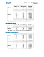
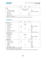
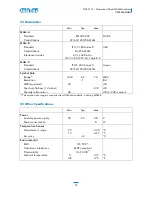
For example, if the DTE-3114 is configured for DVB-C in 256-QAM mode and a symbol rate of
6.875Mbaud, then it follows from the table above that the nominal bit rate is:
R
nominal
=50. 686275MBps
The corresponding maximum allowed input bitrate is:
R
max
= 50.686275 * (1 – 100e-6) = 50.681206Mbps
The DTE-3114 continuously measures the bitrate of the incoming Transport Stream. The system
integrator can use this estimate to verify proper operation. The estimated bitrate is shown in the
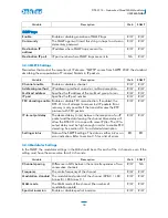
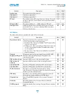
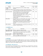
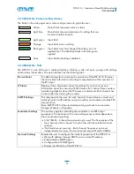
“Device Status” webpage and via SNMP (DTE-MIB: nwRxTsRate).
If the input bitrate is higher than the nominal bitrate, the internal buffers may overflow. This will lead
to an increment of RxIpJitterErrorCounter in the MIB (not visible in the web page). The internal buffer
overflow may result in a lock error. This will increment nwRxLockErrorCounter (in the MIB and also
visible on the IP status webpage). Following a lock error the modulator channel will reset itself and
restart, resulting in a short interruption of the output.
4.3 IP jitter
An idealised TSoIP transmitter generates IP packets that are evenly spaced: the time between IP
packets is constant. When propagating through a network IP packets may incur varying delays
caused by network congestion, timing drift and/or route changes in the network. These will manifest
itself as jitter in the arrival time of the IP packets, so-called “IP jitter”. A non-ideal transmitter adds to
the IP jitter.
The DTE-3114 can tolerate a certain amount of jitter by using an internal buffer to smoothen the
data rate. The size of this buffer determines the maximum IP jitter that can still be accepted. The
buffer is also used for storing IP packets to perform the 2D FEC decoding. This complicates matters,
but it is done to minimize the overall delay. The user can configure the total buffer size by setting the
IP-to-RF delay on the “SMPTE Settings” webpage or via the nwRxIpToOutputDelay MIB object.
The delay from IP input to RF output (IP-to-RF delay) is the sum of:
FEC delay
: The time required to receive a sufficient amount of packets to enable correction of
an IP packet in a 2D FEC block. The FEC delay is automatically computed by the DTE-3114
and depends on the used FEC parameters in the incoming IP stream. The FEC delay is set to
zero if FEC decoding is disabled.
IP jitter tolerance
: The time that the DTE-3114 waits to receive "late" IP packets. Because of this
delay the DTE-3114 can tolerate IP jitter up to the indicated value. The IP jitter tolerance will
be automatically computed from the configured IP-to-RF delay and the FEC delay.
The DTE-3114 measures the maximum amount of jitter and presents it to the user via the delay
factor. The delay factor is the maximum difference, observed at the network input of the DTE-3114,
between the actual arrival of a UDP/RTP packet and the ideal arrival of the packet. The delay factor
is measured every second.
The delay factor can be used to verify that the measured IP jitter does not exceed the maximum jitter
tolerance. If the maximum is exceeded the IP jitter buffer will underflow (increment of

