background image

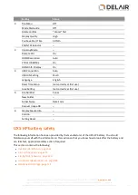
Setting

Value

2

Tile Menu

Off

Mode Dial Guide

Off

Delete confirm.

"Cancel" first

Display Quality

High

Pwr Save Start Time

30 Min

PAL/NTSC Selector

3

Cleaning Mode

Remote Ctrl

On

HDMI Resolution

Auto

CTRL FOR HDML

On

HDMI Info. Display

On

4

USB Connection

Auto

USB LUN Setting

Multi

Language

English

Date/Time Setup

[set correctly at first use]

Area Setting

[set correctly at first use]

5

File Number

Series

New Folder

Folder Name

Date Form

Recover Image DB

6

Display Media Info.

Version

Setting Reset

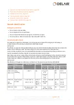
UX5 HP battery safety

The following information has been provided by the manufacturer of the UX5 HP battery. You should
familiarize yourself with the information in this section so that you know how to look after the battery and
can take fast, appropriate safety action if required.
This section contains the following:

l

Hazards identification, page 122

l

First aid measures, page 123

l

Fire fighting measures, page 124

l

Accidental release measures, page 124

l

Handling and storage, page 125

121

Delair-Tech

|

676, Rue Max Planck – 31670 Toulouse-Labège, France

|

Tel: +33 (0) 5 82 95 44 06

|

www.delair.aero

Capital: 238 110,30 € - APE: 3030Z – Intra-Community VAT number: FR90 53 09 69 781 – 530 969 781 R.C.S. Toulouse

This document is the sole property of Delair-Tech and cannot be used or reproduced without the written authorization of Delair-Tech

.

Summary of Contents for UX5 HP

Page 1: ...e Max Planck 31670Toulouse Lab ge France Tel 33 0 5 82954406 www delair aero Capital 238110 30 APE 3030Z Intra Community VAT number FR90530969781 530969781R C S Toulouse This document is the sole prop...

Page 2: ...so chosen that the equivalent isotropically radiated power e i r p is not more than that necessary for successful communication This device complies with Industry Canada license exempt RSS standard s...

Page 3: ...ructions and more information please fill in a contact form at www delair aero or mail a request for recycling instructions to Delair Tech 676 rue Max Planck 31670 Toulouse Lab ge France FCC Declarati...

Page 4: ...O O O O O Power supply X O O O O O Printed circuit board assembly X O O O O O Radio module X O O O O O Chassis O O O O O O Plastic enclosure O O O O O O Paper manual O O O O O O 4 Delair Tech 676 Rue...

Page 5: ...ng the launcher 56 Checking the rover 56 Charging the UX5 HP batteries 59 Charging the tablet batteries 63 Preparing the camera 63 Binding the tracker transmitter and receiver 67 Locating your equipme...

Page 6: ...al support 112 7 Specifications and Settings 113 Operation limitations 114 UX5 HP specifications 115 Launcher specifications 116 Camera specifications 116 Sony a7R camera settings 117 UX5 HP battery s...

Page 7: ...on about operating the components of the Delair UX5 HP Even if you have used other unmanned aviation systems before please read this user guide carefully to familiarize yourself with the UX5 HP 7 Dela...

Page 8: ...ly known coordinates The coordinates of the rover are unknown They are determined relative to the reference position using measurements recorded simultaneously at the two receivers The positioning acc...

Page 9: ...omponents The UX5 HP aerial imaging system comprises the following components l UX5 HP aerial imaging rover l Camera l Ground control station l Launcher l Tracker optional UX5 HP aerial imaging rover...

Page 10: ...alling the Aerial Imaging software Use the Delair Aerial Imaging software to plan manage and monitor your flights The Aerial Imaging Desktop software is installed on an office computer The field versi...

Page 11: ...not already have a license the Delair License Manager opens and prompts you to enter your license key Make sure you have Internet access and then enter your key to activate the software Software noti...

Page 12: ...are the background map adding details such as avoidance zones l Block definition Define one or more blocks to be aerially photographed You can specify the planned direction the rover will fly over the...

Page 13: ...icons page 15 The Home screen When you open the Aerial Imaging software the Home screen appears The Home screen is shown below From this screen you can l Create a new project or import a project Alte...

Page 14: ...g the flight trajectory in software such as Google Earth Exporting the flight trajectory for analysis page 101 Export project data as JXL or CSV TXT files for processing Exporting flight data for proc...

Page 15: ...n the map If you are using the Aerial Imaging Tablet software this icon is not displayed GPS coordinates of the location of the GCS If the GCS has no GPS lock the text no GPS lock is displayed If the...

Page 16: ...d units for speed distance altitude and area l The delimiter for the CSV file exported for processing Network settings Use the settings in the Network group to specify the proxy settings for the Inter...

Page 17: ...rn to the Home screen click in the title bar The following maintenance procedures are available l Rover l Replacing the drive unit l Replacing a servo l Replacing a propeller blade l Replacing the cam...

Page 18: ...ss the update checklist tap The flight checklist is aborted because the software does not allow you to fly when the firmware version is not in sync with the Aerial Imaging software l To start the firm...

Page 19: ...ns and conditions This chapter describes how to plan a project including preparing the project map and creating blocks and flights 19 Delair Tech 676 Rue Max Planck 31670Toulouse Lab ge France Tel 33...

Page 20: ...y can be much improved by using ground control points GCPs if PPK is not available A ground control point is an accurately surveyed coordinate location for a physical feature that can be identified on...

Page 21: ...otion during exposure Selecting the lens The camera can be fitted with different sized lenses The lens size you select depends on the tradeoff you choose between resolution and area coverage l A 15 mm...

Page 22: ...ore information see Network of reference stations page 22 To set up the base station follow the instructions provided by the base station user guide Note It is the user s responsibility to make sure t...

Page 23: ...K Use ground control points GCPs to achieve high accurate results Delair recommends using at least 5 GCPs which are evenly spread around the perimeter of the area to map Creating a project To create a...

Page 24: ...ne map 1 Make sure you have Internet access 2 Click on the map and then enter the location of interest The map shows the area around the location using your preferred online map provider see Changing...

Page 25: ...of the file select it and then click Import The map shows the contents of the file you selected You can have multiple GeoTiff map layers in a project Adding information to the map You can add the foll...

Page 26: ...ining points lines and polygons l GPX files containing points and lines l CSV files containing ground control points GCPs The format for the CSV file is Identifier Latitude Longitude Altitude The coor...

Page 27: ...of the map Click to display the map grid lines Use the button to zoom the map and all of its layers to the best view If you are viewing the map on the tablet and it has a GPS connection the button is...

Page 28: ...tangular area Click the appropriate shape on the toolbar and then draw the area l For a polygon click the mouse at each boundary point l For a rectangle click the mouse on the map A standard sized sha...

Page 29: ...area Note It is not possible to change the block properties when a block is locked To edit the block properties click next to the block name in the list a Select the type of aerial imaging rover you w...

Page 30: ...zone Edit the block to move the flight lines out of the avoidance zone Splitting a block The software estimates the total flight time needed to cover the block The estimated flight time does not inclu...

Page 31: ...icon or cannot be renamed changed or removed However you can copy the block and then edit the copy GSD and height The GSD ground sample distance field specifies the distance on the ground represented...

Page 32: ...f less than 80 as it may prevent large parts of the dataset being adjustable in the Trimble Business Center software due to the lack of tie points especially where the flight height was low or where t...

Page 33: ...t 50 m 164 ft there must be a clear area free of obstacles within 30 to the left and right of the launch direction From 50 m to 280 m From the first 50 m 164 ft and within 280 m 919 ft obstacles must...

Page 34: ...center of the orbit Once the rover has descended 25 m from the cruise flight height the required obstacle free area has a radius of 150 m 462 ft 34 Delair Tech 676 Rue Max Planck 31670Toulouse Lab ge...

Page 35: ...r in the yellow zone shown in the vertical cross section of the landing In addition the landing location must be free of obstacles and meet the minimum size indicated l Linear landing 35 Delair Tech 6...

Page 36: ...taken into account l Linear landing abort clearance l Curved landing abort clearance 36 Delair Tech 676 Rue Max Planck 31670Toulouse Lab ge France Tel 33 0 5 82954406 www delair aero Capital 238110 30...

Page 37: ...he flight in the list and then click below the list Copying a flight is useful if you want to repeat a flight To complete the definition of a flight click next to the flight name and then work through...

Page 38: ...1 Communication timeout The communication timeout value defines when the rover should activate the emergency pattern in case of loss of the communication link l Enter a value in the communication time...

Page 39: ...es with default parameters for example the heading is set into the wind direction If you change the heading the takeoff location is updated accordingly If you use this location in another flight the h...

Page 40: ...ons as you want Click to confirm the added locations l To add a new location using GPS In the Aerial Imaging Tablet software physically go to the landing location and then click If the location you wa...

Page 41: ...faces For more information see Obstacle clearances page 33 6 When the flight has a block linked to it the landing route is displayed a Set the landing entry to use a left or right turn depending on wh...

Page 42: ...t or the map Viewing the flight summary To view the flight summary in the flight menu tap The Flight summary screen looks similar to the example shown below Flight route If a flight will cover more th...

Page 43: ...than the previous block Orbit down in 200 m diameter circles until it reaches the height of the next block and then fly straight to the first waypoint of that block This works if the height of the nex...

Page 44: ...te to the folder where you want to save the flight simulation enter the file name and then click Export The simulated flight trajectory is exported to the selected folder 6 Click to close the Export w...

Page 45: ...d aircraft laws Delair and Authorized Distribution Partners provide comprehensive training for the unmanned aircraft system which includes recommended procedures to ensure the safety for the remote cr...

Page 46: ...rent or additional operational requirements Make sure you are familiar with the appropriate regulations for the country you are operating in If you are flying in the United States see also FAA conditi...

Page 47: ...nd take special care around l Parachute and parasailing jumping areas l Winch areas l High pressure gas releasing units documented in AIPs or NOTAMs l Congested areas for example towns l Check if ther...

Page 48: ...ety precautions described in the documentation provided with the rover l Understanding how to handle emergencies during flight See Handling emergencies during flight page 91 l Understanding the partic...

Page 49: ...er transmitter and receiver n Locating your equipment As part of your flight preparation make sure all equipment is in good condition and well prepared 49 Delair Tech 676 Rue Max Planck 31670Toulouse...

Page 50: ...charger 4 UX5 HP body with camera eBox gBox and top cover 5 UX5 HP battery 6 Tracker transmitter and receiver 7 UX5 HP battery charger and charge cable 8 Extra camera lenses 9 Lens cleaning paper 10...

Page 51: ...s controlled items may not leave the EU customs territory without an export authorization Additional restrictions are also in place concerning the provision of brokering services with regard to dual u...

Page 52: ...load pay are 1 gBox 5 Hot shoe cable 2 Camera 6 GNSS antenna cable 3 Battery 7 Power cable 4 gBox power signal cable 52 Delair Tech 676 Rue Max Planck 31670Toulouse Lab ge France Tel 33 0 5 82954406 w...

Page 53: ...Note Using the incorrect filter will affect the quality of images captured during flight Make sure you are using the correct filter for your camera as detailed below Camera type Filter type Sony a7R R...

Page 54: ...e 60 Inserting the eBox 1 Attach the RF antenna to the underside of the eBox 2 Attach the GPS antenna to the top side of the eBox 3 Insert the eBox into the eBox cavity of the rover body sliding the b...

Page 55: ...power and signal cable is fragile Make sure to handle it with care 4 Connect the GNSS antenna cable to the gBox and firmly tighten the connector using the wrench provided with the gBox Do not over tig...

Page 56: ...wheels are in good condition and move freely If they are worn and must be replaced click in the Home screen select Launcher in the list to the right and then select Replacing the wheels of the launche...

Page 57: ...er is tightly screwed into the body If not gently tighten it taking care not to over tighten it 5 Using first the wet camera wipes and then the dry camera wipes thoroughly clean the camera filter Make...

Page 58: ...blade or refer to the UX5 HP Aerial Imaging Solution Maintenance Guide When in doubt contact your Delair distributor Check the drive unit Make sure the drive unit is l intact l firmly attached If the...

Page 59: ...fety page 121 In this section l Charger overview page 59 l Removing the battery from the rover page 60 l Connecting the charger page 61 l Charging the battery page 62 l Disconnecting the battery page...

Page 60: ...The setting blinks when it is selected l Start the selected charging mode Press and hold for two seconds to start charging Removing the battery from the rover 1 Remove the top cover from the UX5 HP bo...

Page 61: ...11 15 V DC vehicle battery l 100 240 V AC power supply The charger powers on and displays the charge parameters 3 Make sure the charger settings are correct The parameters should be l LiPo manual l C...

Page 62: ...ttery Charging the battery 1 On the charger press and hold the Enter Start key for two seconds The battery starts charging 2 Make sure the battery is properly balanced For more information on how to c...

Page 63: ...ttery to the aircraft 3 Fit the top cover to the UX5 HP body Charging the tablet batteries Charge the batteries according to the instructions provided in the documentation for your tablet Note Make su...

Page 64: ...hecking the Sony a7R camera display The appropriate settings required to obtain good aerial images are set by Delair before the camera is sent to you Before each flight check the camera screen to make...

Page 65: ...0 When using the NIR camera exposure compensation is set to 1 0 for the B W 040 orange filter ISO AUTO ISO is set to Auto the default Setting brightness color settings for the NIR camera To obtain bes...

Page 66: ...to the maintenance procedures for the camera in the Maintenance screen or in the Delair UX5 HP Aerial Imaging Solution Maintenance Guide 2 Loosen the Velcro strap in the payload bay of the rover body...

Page 67: ...are prompted to enter a name for the transmitter Press the MENU OK key to continue 9 Use the navigation keys to enter the name you want to use for the transmitter Confirm each letter using the MENU O...

Page 68: ...UX5 UX5 HP Launcher Quick Start Guide 68 Delair Tech 676 Rue Max Planck 31670Toulouse Lab ge France Tel 33 0 5 82954406 www delair aero Capital 238110 30 APE 3030Z Intra Community VAT number FR905309...

Page 69: ...ost flight checklist n Disassembling the launcher This chapter describes the tasks required in the field to complete a successful flight with good image data 69 Delair Tech 676 Rue Max Planck 31670Tou...

Page 70: ...e following weather phenomena occurs before the flight l Strong wind l Heavy rain hail l Hurricane tornado or any kind of whirlwind l Thunder and lightening l Snow If there are sudden weather changes...

Page 71: ...ight checklist tab starts with an overview of the flight that you have selected and will execute Note More information about the steps that require special care is given in the following sections Read...

Page 72: ...the software to check if the modem is connected When the connection to the modem is established the software automatically moves to the next step in the flight checklist Connecting the battery Note M...

Page 73: ...checklist and either update the project plan or use the correct size of lens Preparing the camera 1 Insert an empty SD card into the camera 2 Turn on the camera and check the camera screen to make su...

Page 74: ...of the payload bay Connect the hot shoe cable in the rover to the hot shoe of the camera Secure the camera using the Velcro straps For more information see Inserting the camera page 66 Note After inse...

Page 75: ...freely and are not obstructed in any way Impaired movement of the elevons can cause the servo motor to burn up When the elevon response is checked the button is enabled Assembling the launcher 1 Unfo...

Page 76: ...pproximately 2 3 of the length of the launch slide Turn the knob to the right to tighten 76 Delair Tech 676 Rue Max Planck 31670Toulouse Lab ge France Tel 33 0 5 82954406 www delair aero Capital 23811...

Page 77: ...At the same time pull the release handles gently upward This is safest done with two people with one person carefully winding the crank counter clockwise to counteract the force on the elastics 5 Posi...

Page 78: ...r causing serious personal injury and damage to the rover or launcher CAUTION Never launch without the rover sitting on the dock as it will damage the launch dock The design of the launcher takes into...

Page 79: ...the artificial horizon in the status panel of the Aerial Imaging software changes The airspeed should reach at least 50 kph 31 mph Positioning the propellers WARNING Always take care when touching th...

Page 80: ...tion refer to the maintenance procedures in the Maintenance screen or refer to the UX5 HP Aerial Imaging Solution Maintenance Guide 3 Remove the crank Verifying the position of the aircraft on the lau...

Page 81: ...y pin WARNING Always take care to avoid contact with the propeller blades If the rover receives a sudden shock while armed the motor can unexpectedly start causing the propeller blades to move Contact...

Page 82: ...t allow you to arm if the following errors are reported l The eBox is not in the correct state l Rover battery life is less than 35 l The takeoff sensor is not OK this means that the yaw pitch and rol...

Page 83: ...the launch dock The design of the launcher takes into account the weight of the rover sitting on the launch dock 3 If an obstacle such as a person or animal suddenly appears in the obstacle clearance...

Page 84: ...learance l Keep an eye on changing weather conditions l Locate the rover on the tablet screen l Monitor the flight telemetry on the GCS After takeoff the rover climbs to the specified cruise height On...

Page 85: ...atellites l Monitor that the number of eBox feedback events increases as expected l Monitor the wind speed and direction measured by the eBox l Compare the actual airspeed with the desired airspeed wh...

Page 86: ...change the landing parameters To change the landing parameters during flight 1 Select the Flights tab The Flights tab shows the landing properties for the flight 2 Depending on the situation do one o...

Page 87: ...eld in the Autopilot settings group of the Settings screen or if the communication link is poor and communication packets are being received intermittently then from the moment that communication is l...

Page 88: ...u tap the rover immediately terminates its flight plan and initiates a normal landing sequence It flies at the desired flight height to the entry point which is located 300 m 984 ft from the landing l...

Page 89: ...ity is observed When you tap the rover begins orbiting its current location at the desired flight height in 200 m 656 ft diameter circles Mapping is paused If the Hold command is initiated during the...

Page 90: ...nding If the desired height is not yet reached at the orbit location the aircraft circles upward until the desired height is reached When in the Right pattern you can adjust the rover s height by 10 m...

Page 91: ...will not cross the flight path of the rover 1 Assess the situation 2 Tap or to move the rover to a safe position The flight path of the approaching aircraft and the rover are converging 1 Assess the...

Page 92: ...ects if the rover is in the air and a message asks if you want to connect to the rover and continue the flight 2 Tap to confirm The Aerial Imaging software downloads the existing flight plan from the...

Page 93: ...nding To do this you must l Have visual contact with the rover at all times l Observe the zone of operation for the rover and look out for other aerial objects l Ensure obstacle clearance l Locate the...

Page 94: ...ess the Menu OK key to confirm 4 Fold out the four antennas on the receiver and then place the receiver on the palm of your hand taking care not to touch any of the antennas 5 Increase the gain as muc...

Page 95: ...over when the eBox is not in standby mode When the eBox is not in standby mode the motor can unexpectedly start causing the propeller blades to move Contact with moving propeller blades can result in...

Page 96: ...ith incorrect specifications see Locating your equipment page 67 or incorrect camera settings contact your Delair distributor 13 Validate the block s that were successfully mapped during the flight 14...

Page 97: ...detach the V support turn the knob upward and then slide the pins out of the holes in the launch slide Remove the lock pin on the V support to fold the legs and then reinsert the lock pin CAUTION Tak...

Page 98: ...ting the flight trajectory for analysis 98 Delair Tech 676 Rue Max Planck 31670Toulouse Lab ge France Tel 33 0 5 82954406 www delair aero Capital 238110 30 APE 3030Z Intra Community VAT number FR90530...

Page 99: ...ktop software To be able to do this you must export the project from the Aerial Imaging software on the tablet and import it to the Aerial Imaging Desktop software To export the project from the Aeria...

Page 100: ...o change the image type select the NIR option l whether to correct images for vignetting The option to correct for vignetting is selected by default if flight conditions were such that Delair strongly...

Page 101: ...oints Both outputs can be viewed in software such as in Google Earth 4 Click 5 Select the flight to export and click 6 Navigate to the folder where you want to save the exported file Enter the file na...

Page 102: ...ED status n Technical support 102 Delair Tech 676 Rue Max Planck 31670Toulouse Lab ge France Tel 33 0 5 82954406 www delair aero Capital 238110 30 APE 3030Z Intra Community VAT number FR90530969781 53...

Page 103: ...he rover and redo the checklist eBox logging has not started If the issue does not resolve itself cancel the checklist Disconnect the battery from the rover and redo the checklist The GCS has no GPS c...

Page 104: ...ver should be in standby mode If it is not disarm the rover by pressing the Mode button three times three flashes taking care to avoid the propellers 2 Tap and complete the post flight checklist 3 Rep...

Page 105: ...There will be communication issues at checklist steps that required communication between the modem and the eBox To resolve these issues 1 Make sure that the RF antennas are well connected and the co...

Page 106: ...e is an invalid command in the flight plan 18 There is an autopilot configuration problem 19 There is an autopilot configuration problem 20 There is an autopilot configuration problem 21 There is an a...

Page 107: ...utopilot hardware problem 58 There is an accelerometer sensor hardware problem 59 There is a GPS receiver hardware problem 60 There is an autopilot configuration problem 61 There is an airspeed sensor...

Page 108: ...dware problem 91 There is a roll gyro sensor hardware problem 92 There is a yaw gyro sensor hardware problem 93 There is an accelerometer sensor hardware problem 94 There is an accelerometer sensor ha...

Page 109: ...ing off the motor as soon as possible to avoid motor damage To manually power off the rover tap the button in the Aerial Imaging software If that does not work press and hold the Mode button on the eB...

Page 110: ...arted CONTACT BREAK This error occurs when the connection between the battery and the charger is interrupted If the message appears Then Before charging Charging cannot be started When charging The ch...

Page 111: ...Steady eBox is armed The diagram below shows the manual intervention to go from one state to another 111 Delair Tech 676 Rue Max Planck 31670Toulouse Lab ge France Tel 33 0 5 82954406 www delair aero...

Page 112: ...satellites Red LED single flash A trigger command has occurred Technical support If you have an issue and cannot find the information you need in the product documentation contact your Delair distribu...

Page 113: ...ttings n UX5 HP battery safety 113 Delair Tech 676 Rue Max Planck 31670Toulouse Lab ge France Tel 33 0 5 82954406 www delair aero Capital 238110 30 APE 3030Z Intra Community VAT number FR90530969781 5...

Page 114: ...clouds Clear of clouds and always within line of sight Flight visibility 5000 m 16400 ft Operator UAS visibility Visual line of sight Weather limitations Light rain is acceptable Avoid hail snow and h...

Page 115: ...nergy capacity 6600 mAh Nominal voltage 14 8 V Maximum voltage 16 8 V Storage voltage 15 6 V Battery charging current 3 A Battery charging time if fully discharged Maximum 2 5 hours Operating temperat...

Page 116: ...3 0 Dimensions width x height x depth 126 9 x 94 4 x 48 2 mm 5 0 x 3 7 x 1 9 Weight body only 407 g 0 9 lb Battery charging time Approximately 210 minutes using a Sony charger when battery is fully di...

Page 117: ...l Shoot Mode Setting Value Shoot Mode S Shutter priority Menu settings Camera settings Setting Value 1 Image Size L 36M Aspect Ratio 3 2 Quality Fine File Format movie AVCHD 2 Record Setting movie 50i...

Page 118: ...Style Standard Picture Effect Off 5 Focus Magnifier Long Exposure NR Off High ISO NR Normal Smile Face Detect Off Soft Skin Effect Off 6 Color Space sRGB 7 Auto Slow Shut movie Off Audio Recording Off...

Page 119: ...nable 4 AF w shutter Off AEL w shutter Off Exp comp set Ambient only Reset EV Comp Reset Bracket order 0 5 Face Registration APS C Size Capture Off AF Micro Adj AF Adjustment Set Clear Off Lens Comp S...

Page 120: ...cation There are no relevant settings set in the Application menu Playback Setting Value 1 View Mode 2 Display Rotation Off Setup Setting Value 1 Monitor Brightness Manual Viewfinder Bright Manual Fin...

Page 121: ...n provided by the manufacturer of the UX5 HP battery You should familiarize yourself with the information in this section so that you know how to look after the battery and can take fast appropriate s...

Page 122: ...Risk of exposure is only in case of abuse mechanical thermal electrical leading to the activation of safety valves and or the rupture of the battery containers Electrolyte leakage electrode materials...

Page 123: ...lear out fumes gases In all cases where first aid is applied seek medical attention Eye contact l Flush with plenty of water eyelids held open for at least 15 minutes Skin contact l Remove all contami...

Page 124: ...ishing media Suitable CO2 Dry chemical or foam extinguishers Not to be used Type D extinguishers Special exposure hazards Following cell overheating due to external source or due to improper use elect...

Page 125: ...ttery service life Battery exposure to temperatures in excess of 130 C 266 F will result in the battery venting flammable liquid and gases Batteries should be separated from other materials and stored...

Page 126: ...F 20 to 60 C 4 to 140 F During charge 0 to 45 C 32 to 113 F 0 to 45 C 32 to 113 F Stability and reactivity Conditions to avoid Heat above 60 C 140 F or incineration Deform mutilate crush pierce disas...

Page 127: ...exempted from the hazardous waste disposal standards under Universal Waste Regulations Disposal of large quantities of lithium ion batteries or cells may be subject to Federal State or Local regulatio...

Page 128: ...nd 3 Release of contents Special shipping information This battery has been tested to Section 38 3 of UN Manual of Tests and Criteria The amount of lithium contained in these batteries is below the li...

Page 129: ...ed the operator s manual is considered acceptable to the FAA The operator s manual and this grant of exemption must be maintained and made available to the Administrator upon request If a discrepancy...

Page 130: ...requirements specified in 14 CFR 61 56 in an aircraft in which the Operator is rated on his or her pilot certificate 16 Prior to operating for hire the operator must have completed Delair s five day U...

Page 131: ...e conducting operations the radio frequency spectrum used for operation and control of the UA must comply with the Federal Communications Commission FCC or other appropriate government oversight agenc...

Page 132: ...en the land owner controller grants such permission and the Operator makes a safety assessment of the risk from operations closer to these objects 34 All operations shall be conducted over private or...

Page 133: ...antenna and receiver set up on a known location specifically to collect data to be used in postprocessing rover files During a PPK survey data is collected so that baselines the position of one receiv...

Page 134: ...ystem GNSS This is the standard generic term for satellite navigation systems that provide geospatial positioning with global coverage ground control point An accurately surveyed coordinate location f...

Page 135: ...ping to make measurements between objects pitot tube The sensor used by the aircraft to detect airspeed It must be kept clean and free of obstructions to operate correctly postprocess To process satel...

Page 136: ...ient aerial photo stations to each other and reference them to the ground based on autonomous GNSS positions recorded when the photo images are taken tracker The tracker consists of a transmitter inse...

Page 137: ...Toulouse Lab ge France Tel 33 0 5 82954406 www delair aero Capital 238110 30 APE 3030Z Intra Community VAT number FR90530969781 530969781R C S Toulouse This document is the sole property of Delair Tec...

Reviews: