14
English
Italiano
Descrizione funzioni
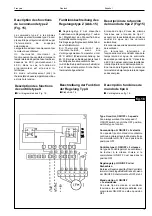
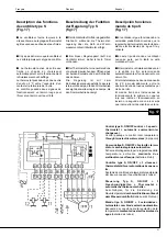
comando tipoT e Y
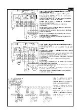
(fig. 13 - 14)
■
Regolazione sul ventilatore
Quando il termostato chiede caldo o fred-
do il ventilatore gira alla velocità selezio-
nata ed a set point soddisfatto si ferma.
Con il comando montato a bordo mac-
china, a ventilatore fermo per raggiunto
set-point, il termostato non percepisce
immediatemente variazioni di tempera-
tura a causa dell'effetto di stratificazione
dell'aria: occorre azionare il ventilatore
per un breve periodo onde permettere al
sensore di rilevare la temperatura am-
biente; ciò viene effettuato tramite un
timer inserito sulla scheda elettronica
che avvia il ventilatore ciclicamente.
■
Regolazione sull'acqua
Il ventilatore gira sempre alla velocità
selezionata.
La valvola sull'acqua viene aperta quan-
do il termostato chiede caldo o freddo e
viene chiusa quando il termostato è sod-
disfatto. In questo tipo di installazione
deve essere disabilitato il timer che attiva
ciclicamente il ventilatore a set-point sod-
disfatto (vedi regolazione sul ventilatore).
Per disabilitare il timer occorre rimuove-
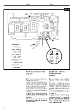
re il cavallotto JP2 posto sul circuito
stampato del comando.
■
Sul comando sono inserite due
segnalazioni di funzionamento: la prima
visualizzata da una lampadina rossa che
indica il funzionamento invernale, la se-
conda visualizzata da una lampadina ver-
de che indica il funzionamento estivo.
Con il comando montato a bordo macchi-
na a ventilatore fermo per raggiunto set-
point, viene azionato il timer e contempo-
raneamente viene abilitata anche la lam-
padina di colore opposto alla condizione
di funzionamento. Es.: se il comando è
posizionato in inverno è accesa la lampa-
dina rossa e contemporaneamente viene
accesa anche la lampadina verde per il
tempo di funzionamento di "ON" del timer.
Questa condizione non è sinonimo di mal
funzionamento della macchina, ma indi-
ca che il controllo elettronico sta verifi-
cando se la temperatura rilevata dal
sensore è ottimale.
La funzione qui sopra descritta non è abilitata
quando il comando è collegato con regola-
zione sull'acqua o con montaggio a parete.
■
Il comando tipo T deve essere completa-
to con uno dei seguenti collegamenti:
•
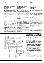
cambio stagionale a distanza (fig. 13)
•
funzionamento solo in riscaldamento,
(cavallotto tra i morsetti 7 e 5)
•
funzionamento solo in raffreddamento,
(cavallotto tra i morsetti 7 e 6).
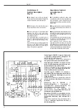
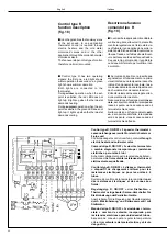
Control type T and Y
function description
(fig. 13 - 14)
■
Control through fan
When the thermostat demands heating
or cooling, the fan runs at the set speed
and stops when the set-point is reached.
With unit-mounted control, and fan
switched off, because the set-point has
been reached, the thermostat does not
immediately sense temperature
changes due to the stratification of the
air: it is necessary to operate the fan for
a short period allowing the sensor to
measure room temperature; this is done
with a timer on the electronic card which
cycles the fan on and off.
■
Control through water
The fan always runs at the set speed.
The water valve opens when thermostat
demands heating or cooling and is
closed when the thermostat is satisfied.
At this point the timer, which switches the
fan on and off, has to be closed (see
control through the fan).
To deactivate the timer it is necessary to
remove the jumper JP2 positioned on
the printed circuit of the control.
■
The control has two operating signals:
the first one, a red light, shows the winter
operation, the second one, a green light,
shows the summer operation.
With unit-mounted control and fan
switched off, because the set point has
been reached, the timer is enabled, and
at the same time the corresponding to
the opposite operating condition LED
lights up.
Example: if the control is set to winter
operation the red LED lights up and at
the same time the green LED comes on
when the timer is operating.
This does not mean that the unit is
malfunctioning, but indicates that the
electronic control is checking if the tem-
perature felt by the sensor is optimal.
The above function does not apply when
control is connected for water flow
control or when it is wall mounted.
■
Control type T must be completed with
one of the following connections:
• remote seasonal changeover switch
(Fig. 13)
• heating only operation (jumpered via
terminals 7 and 5)
• cooling only operation (jumpered via
terminals 7 and 6).

