24
English
Italiano
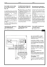
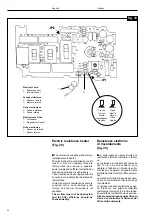
Uso del sensore (fig.19)
Sensore interno
■
E' usato in tutti i tipi di installazione dove
il montaggio del comando venga effettua-
to a parete.
Per renderlo attivo occorre chiudere il ca-
vallotto JP1 montato sul circuito stampato
posto vicino al sensore. La sua posizione
all'interno della scatola è stata studiata in
modo che il sensore venga ventilato per
convenzione naturale (effetto camino)
minimizzando l'effetto del riscaldamento
dovuto ai componenti elettronici.
Sensore remoto
■
E' usato in tutti i tipi di installazione dove
il montaggio del comando venga effettua-
to a bordo macchina.
Per renderlo attivo occorre aprire il caval-
lotto JP1 montato sul circuito stampato
posto vicino al sensore (questa operazio-
ne è effettuata dal costruttore della sche-
da elettronica per cui il comando ver-rà
consegnato configurato con JP1 aperto).
■
Entrambi i sensori sono sempre montati
sulla scheda elettronica. In funzione del
tipo di applicazione usata verrà abilitato o
uno o l'altro tipo (tabella1).
Uso dei cavallotti JP1 - JP2
(TAB I)
■
Il comando tipo U non è provvisto di
cavallotto.
■
I comandi tipo Y e T sono provvisti di un
cavallotto JP1 utilizzato dal costruttore
per la taratura del termostato e dall'instal-
latore per la selezione del tipo di sensore
(esterno o interno).
Nell'applicazione con montaggio del co-
mando a bordo macchina JP1 deve esse-
re aperto.
Nell'applicazione con montaggio del co-
mando a parete JP1 deve essere chiuso.
Entrambi i comandi tipo Y e T sono prov-
visti della funzione timer; questa funzione
è attiva quando il cavallotto JP2 è chiuso.
Con il cavallotto JP2 aperto si abilita il
comando a lavorare con regolazione sul-
l'acqua o con montaggio a parete.
■
I comandi tipo R e S sono provvisti di un
cavallotto JP1 utilizzato dal costruttore
per la taratura del termostato e
dall'installatore per la selezione del tipo di
sensore (esterno o interno).
Nell'applicazione con montaggio del co-
mando a bordo macchina JP1 deve esse-
re aperto.
Nell'applicazione con montaggio del co-
mando a parete JP1 deve essere chiuso.
Entrambi i comandi tipo R e S non sono
provvisti della funzione timer, per cui il
cavallotto JP2 non è montato.
■
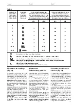
Una visione completa dei tipi di instal-
lazione è riportata in TAB. 1
■
Nota: Tutti i comandi vengono forniti
nella configurazione standard con JP1
aperto e JP2 chiuso.
Sensor use (fig. 19)
Internal sensor
■
This is used on all units with wall-
mounted control.
To activate the sensor, it is necessary to
close jumper JP1 mounted on the printed
circuit board near the sensor. Its position
inside the box has been selected to allow
sensor ventilation through natural
convection (chimney effect) minimizing
the heating effect from electronic
components.
Remote sensor
■
This is used on all fan coils with unit-
mounted control.
To activate the sensor, it is necessary to
open jumper JP1 mounted on the printed
circuit board near the sensor (the sensor
is supplied by the electronic card manu-
facturer with JP1 already open).
■
Both sensors are always mounted on
the electronic card. Depending on the
type of application used one of the two will
be activated (table1).
Jumper use JP1 - JP2
(TAB I)
■
Jumpers are not supplied on control
type U.
■
Controls types Y and T include jumper
JP1, used by the manufacturer for
thermostat setting and by the installer for
sensor selection (outside or inside).
With unit-mounted controls JP1 must be
open.
If the control is mounted on the wall JP1
must be closed.
Both Y and T controls include the timer
function; this function is activated when
jumper JP2 is closed;
When jumper JP2 is open the control
works through water flow control or is wall-
mounted.
■
Control types R and S include jumper
JP1 used by the manufaturer for
thermostat setting and by the installer for
sensor selection (outside or inside).
If the control is mounted on the unit JP1
must be open.
If the control is wall-mounted JP1 must be
closed.
Both R and S controls are not provided
with the timer function, therefore jumper
JP2 is not mounted.
■
A complete list of installation types is
given in Table 1
■
Note: All controls are supplied with
standard configuration, with JP1 open
and JP2 closed.


