4
English
Italiano
Unità verticale a pavimento
■
L'unità per il fissaggio a pavimento dovrà
essere provvista di piedi di sostegno.
Per il posizionamento e la foratura utilizzare
la dima a corredo nell'imballo.
Ultimare l'installazione eseguendo gli allac-
ciamenti idraulici ed elettrici come da sche-
ma riportato all'interno del quadro elettrico.
Unità verticale sospesa a
parete (fig. 4)
■
Per il posizionamento dell'unità utilizzare
la dima a corredo nell'imballo.
Eseguire le quattro forature per i tasselli ad
espansione.
■
Se l'unità è priva di zoccoli deve essere
sollevata dal pavimento almeno di 100 mm.
Predisporre le viti superiori, agganciare
l'unità base e fissarla con 4 viti.
■
Ultimare l'installazione eseguendo gli al-
lacciamenti idraulici ed elettrici come sche-
ma riportato all'interno del quadro elettrico.
Unità orizzontale (fig. 5)
■
Per il posizionamento dell'unità a soffitto,
utilizzare la dima a corredo nell'imballo.
Eseguire le quattro forature per i tasselli ad
espansione.
Agganciare l'unità ai tasselli ad espansione
applicati al soffitto e regolare la chiusura
delle 4 viti, in modo da dare all'unità una
leggera pendenza per agevolare il drenag-
gio dell'acqua di condensa (fig. 5).
Floor mounted vertical unit
■
The floor mounted unit must be provided
with supporting feet.
For positioning and drilling use the template
supplied with the packaging.
To complete the installation make electric
and water connections as per the diagram
inside the electric panel.
Wall-mounted vertical unit
(fig. 4)
■
To position unit use the template supplied
with the packaging.
Drill four holes for the screw anchors.
■
Raise unit at least 100 mm if it is not
provided with cover panels.
Position the upper screws, hook on the
base unit and fix it with 4 screws.
■
To complete the installation make electric
and water connections as per the diagram
inside the electric panel.
Horizontal unit (fig. 5)
■
Use the template supplied with the
packaging for ceiling mounting of the unit.
Drill four holes for the screw anchors.
Hook the unit on the screw anchors in the
ceiling and adjust the 4 screws, in order to
give the unit a little slope to facilitate the
draining of the condensate water (fig. 5).
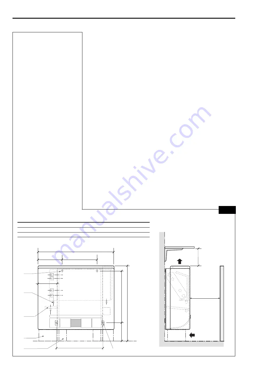
fig. 4
Vertical wall-mounted unit
➀
No 2 10x15 slots for wall fastening
➁
Drain connection 20 mm o. d.
➂
Auxiliary drain pan (optional)
20 mm o. d. drain conn.
√
Cover panel (optional)
➄
Support feet (optional)
≈
No 2 10x6 slots for wall fastening
Unità verticale sospesa a parete
➀
N
°
2 asole 10x15 per fissaggio a parete
➁
Scarico condensa ø est. 20 mm
➂
Bacinella ausiliaria (accessorio)
ø est. attacco 20 mm
√
Zoccoli (accessori)
➄
Piedi (accessori)
≈
N
°
2 asole 10x6 per fissaggio a parete
Unité verticale au mur
➀
N
°
2 boutonnières 10x15
pour la fixation au mur
➁
Drainage de l'eau de condensation
ø ext. 20 mm
➂
Bassin de drainage auxiliaire (accessoire)
ø ext. connex. 20 mm
√
Socles (accessories)
➄
Pieds de support (accessories)
≈
N
°
2 boutonnières 10x6
pour la fixation au mur
Vertikale Wandeinheit
➀
Langlöcher (10x15)
zur Befestigung an der Wand
➁
Kondenswasserabfluß
Außendurchmesser 20 mm
➂
Zusatz-Ablaufwanne (Zubehör)
Außendurchmesser
Anschluß 20 mm
√
Fußleisten (Zubehör)
➄
Stützfüße (Zubehör)
≈
Langlöcher (10x6)
zur Befestigung an der Wand
Unidad vertical de pared
➀
N
°
2 aberturas 10x15 para fijar en la pared
➁
Colector líquido de condens. ext. 20 mm
➂
Deposito auxiliar (accessorio)
ext. conexión 20 mm
√
Zócalos (accesorios)
➄
Pies (accesorios)
≈
N
°
2 aberturas 10x6 para fijar en la pared
230
B
445
168
651
185
C
A
➄
➂
➁
√
➀
≈
500 min.
150
min.
AWX
01
02
03
04
05
06
08
10
A
mm
720
720
920
920
920
1120
1320
1320
B
mm
332
332
532
532
532
732
932
932
C
mm
432
432
632
632
632
832
1032
1032

