16
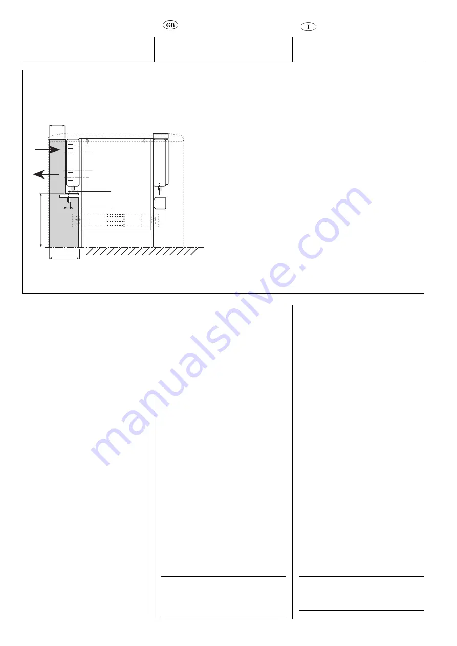
Front view /
Vista frontale / Vue de front / Vorderansicht / Alzado
Space for water connections /
Spazi per allacciamenti idraulici / Espace nécessaire pour les
branchements d’eau /
Platz für Wasseranschlüsse / Espacio para conexiones hidráulicas
IN
OUT
Cool Ø 3/4” gas female
Heat Ø 1/2” gas female
Condensate drain
Auxiliary drain pan
(accessory)
Floor
196 mm
302 mm
130 mm
Ø 20 mm
Ø 20 mm
Water connections
INGRESSO
USCITA
Freddo Ø 3/4” Gas femmina
Caldo Ø 1/2” Gas femmina
Scarico condensa
Bacinella ausiliaria
(accessorio)
Pavimento
ENTRÉE
SORTIE
Froid Ø 3/4” gaz femelle
Chauffage Ø 1/2” gaz femelle
Bac à condensats
Bac à condensats auxiliaire
(accessoire)
Sol
EIN
AUS
Kühlung Ø 3/4” -
Anschluss mit Innengewinde
Heizung Ø 1/2” -
Anschluss mit Innengewinde
Kondensatablauf
Hilfs-Ablaufwanne (Zubehör)
Fußboden
Entrada IN
Salida OUT
Frío hembra Ø 3/4” gas
Calor hembra Ø 1/2” gas
Recogida de condensado
Bandeja auxiliar de recogida de condensado
(accesorio)
Suelo
Le tubazioni dell’impianto idrico potranno
arrivare sia da pavimento che da parete
utilizzando gli spazi secondo la figura.
La batteria sull’unità viene fornita con i
collegamenti idraulici posizionati come da
richiesta in fase d’ordine.
E’ comunque possibile invertire in cantiere la
posizione degli attacchi nel seguente modo:
• rimuovere il quadro elettrico;
• svitare le 6 viti autofilettanti e rimuovere
la bacinella anteriore;
• svitare le 2 viti di fissaggio della batteria
alla struttura, necessarie per il collega-
mento della messa a terra della batteria;
• sfilare la batteria sganciandola per mezzo
delle linguette in gomma e ruotarla
orizzontalmente di 180°;
• posizionare la batteria nella sua nuova
sede agganciandola con le apposite
linguette in gomma;
• rimontare la bacinella anteriore con le 6
viti autofilettanti;
• riavvitare le 2 viti di fissaggio della
batteria alla struttura, necessarie per il
collegamento della messa a terra della
batteria;
• posizionare il quadro elettrico sul lato
opposto agli attacchi della batteria;
• posizionare il sensore di temperatura
nella apposita sede sigillando con stucco
nelle versioni tangenziali;
• inserire il comando nelle apposite
linguette bloccandolo con la staffetta a
corredo (vedi paragrafo “Fissaggio
comando”).
NOTA:
Rivestire i tubi dei collegamenti con del
materiale anticondensa tipo polietilene o
moltoprene espanso di spessore 5-10 mm.
Collegamenti idraulici
Water piping can enter either from the floor
or from the wall. Leave the space shown in
the figure.
The unit coil can be supplied with water
connections positioned as requested.
However field conversion of the
connections is achieved quite simply as
follows:
• Remove the control box panel;
• Unscrew the 6 self-threading screws and
remove the front drain pan;
• Unscrew the two screws holding the heat
exchanger to the structure, necessary for
earthing the coil;
• Remove the coil by unhooking it with the
rubber tabs and turn it horizontally
through 180°.
• Place the coil into its new position by
hooking it using the special rubber tabs;
• Refit the front drain pan with the 6 self-
threading screws;
• Retighten the two screws holding the
heat exchanger to the structure,
necessary for earthing the coil;
• Position the control box panel opposite
the coil connections.
• Pass the sensor through the special hole
and seal with sealing material in the
tangential fan versions;
• Position the control into the tabs
provided,, blocking it with the supplied
metal plate (see paragraph “Controls”).
NOTE:
The connection pipes must be insulated
with a condensation-proof material such as
polyurethane, propylene or neoprene of 5
to 10 mm thickness.


