background image

30

Comandi

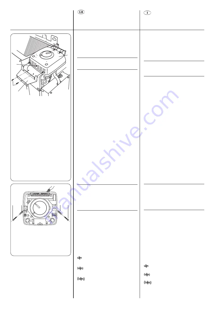
Comando a bordo macchina

Operazioni preliminari:

• Togliere l’alimentazione elettrica.
• Rimuovere il mobile.
• Accedere alla parte superiore del quadro

elettrico posizionando il comando come
da figura.

IMPORTANTE:
Eseguire la configurazione dei “dip
switch” prima di chiudere il comando
con il relativo coperchio.

• Aprire il quadro elettrico ed eseguire i

collegamenti del cavo comando alla
morsettiera. Il cavo comando è provvisto
di due connettori di tipo polarizzato per
evitare errori di collegamento.

• Inserire la sonda temperatura

nell’apposita sede.

• Inserire il comando nelle apposite

linguette e fissare la staffa con le 2 viti 

.

Comando a parete

• Predisporre i collegamenti elettrici tra la

morsettiera del comando e il quadro
elettrico del ventilconvettore.

• Togliere il coperchio del comando

rimuovendo la vite di chiusura posizionata
nella parte inferiore.

• Scollegare il cavo di collegamento in

dotazione e relativo sensore (aria) in
quanto non più necessari.

• Configurare il cavallotto JP1 in posizione

“sensore interno attivo” (vedere paragrafo
“Uso del sensore di temperatura”).

• Fissare il comando a parete contrassegnando

 i

punti di foratura (quando necessario).

• Eseguire le forature sui punti contrassegnati

in precedenza. Evitare di eseguire forature
con comando posizionato a parete.

• Fissare il comando utilizzando gli appositi

tasselli.

IMPORTANTE:
• Tutti i collegamenti tra l’unità e il

comando devono essere eseguiti sotto
traccia.

• Manipolare il comando con estrema

cautela evitando di toccare i componenti
elettronici per non danneggiarli.

Rimontare il coperchio del comando e la
vite tolta in precedenza.

Utilizzo

Selettore acceso/spento e velocità di
ventilazione
OFF

in questa posizione il comando è
spento e tutte le funzioni sono
disabilitate.
Se la funzione antigelo (frost-
protection) viene selezionata
tramite l’apposito “dip-switch”
(microinterruttore), questa diventa
attiva anche con comando in
posizione 

OFF

.

con il selettore in questa posizione,
il ventilatore gira alla bassa velocità.

con il selettore in questa posizione
il ventilatore gira alla media velocità.
con il selettore in questa posizione
il ventilatore gira alla alta velocità.

AUTO

il comando mantiene la temperatura
i

mpostata commutando automaticamente

la velocità di ventilazione.

Controls

Unit-mounted control

Preliminary operations:

• Disconnect the main power supply.
• Remove cabinet.
• Access upper part of control box panel

positioning the control as shown.

IMPORTANT:
Make dip switch configuration before
closing the control cover.

• Open the control box panel, carry out

connections from the control to the
terminal block.
The cable from the control has two
polarized connectors to avoid risk of
connection errors.

• Place the temperature sensor in the

proper location.

• Place the control in the proper metal plate

tabs and fix it with the 2 screws 

.

Wall-mounted control

• Prepare electrical connections between

the control terminal block and the unit
control box panel.

• Remove the control cover, unscrewing

the screw located in the bottom part.

• Disconnect the connection cable

(provided) and corresponding sensor (air)
as they are no longer needed.

• Configure jumper (JP1) to the “activated

internal sensor” position (see paragraph
“Use of temperature sensor”).

• Secure the control to the wall, marking

the drill holes (if necessary).

• Drill the holes previously marked.

Avoid drilling with the control already
placed on wall.

• Fix the control using the screw anchors.

IMPORTANT:
• All connections between the unit and

the control must be placed into a
proper plastic conduit.

• Handle the control with extreme care.

Do not touch electronic components
to avoid damaging them.

• 

Replace the control cover and the screw
previously removed.

Use

ON/OFF/fan speed selector

OFF

In this position the control is OFF
and all functions are disabled.
If the frost protection function is
selected by the dip-switch, this is
activated even if the control is in

OFF 

position.

With selector in this position, the
fan operates at low speed.

With selector in this position, the
fan operates at medium speed.

With selector in this position, the fan
operates at high speed.

AUTO

The control maintains the selected
temperature, acting automatically
on the fan speed.

Control

Screw to close
the control

Control cable

Control box
panel

Metal plate to
fix the control

Screws

Comando

Vite chiusura
comando

Cavo comando

Quadro elettrico

Staffa fissaggio
comando

Viti

Commande

Vis pour fermer la
commande

Câble de la
commande

Panneau de
commande

Plaque métallique
pour fixer la
commande

Vis

Regelung

Schraube zurm
Schließen der
Regelung

Regelungs-
Kabel

Schaltkasten

Metallplatte zur
Befestigung der
Regelung

Schrauben

Control

Atornillar para
cerrar el control

Cable de
control

Cuadro eléctrico

Placa metálica
para fijar el
control

Tornillos

  Screw

Screw anchor

  Vite

  Tassello

  Tornillo

  Taco

  Vis

  Cheville d’ancrage

  Schraube

  Dübel

Summary of Contents for Carrier 42N

Page 1: ...VETTORI Manuale d installazione VENTILO CONVECTEURS Manuel d installation VENTILATOR KONVEKTOREN Installationsanweisungen UNIDADES FAN COIL Manual de instalaci n 42N L L O Y D S R E G I S TER QUALIT Y...

Page 2: ...ticale a parete Scarico condensa esterno 20 mm Zoccoli accessori Piedi accessori Asole per fissaggio orizzontale a soffitto Rainures de fixation murale verticale Raccordement de vidange des condensats...

Page 3: ...8 28 Sommaire page Cotes et poids 2 3 Limites de fonctionnement 4 Caract ristiques lectriques 5 Caract ristiques techniques de la r sistance lectrique 5 Mat riel fourni 5 G n ralit s 6 7 Attention vit...

Page 4: ...emperatur 32 C Netzstromversorgung Einphasige Nennspannung 230V 50Hz Betriebsspannungsbereich min 198V max 264V Max statischer Druck 2 mit Radialventilator 60 Pa Gr e 16 70 Pa Gr e 25 33 43 50 60 75 M...

Page 5: ...are paragrafo Collegamenti elettrici Note pour le type de c bles utiliser voir le paragraphe Branchements lectriques Anmerkung F r die zu verwendenden Kabeltypen siehe Abschnitt Elektrische Anschl sse...

Page 6: ...i spazi minimi di manutenzione consigliati vedi disegno Considerare una posizione che permetta una buona distribuzione dell aria nell ambiente Installare l unit in modo che l acqua di condensa possa f...

Page 7: ...t einen Antrag bei der Spedition einreichen Besch digte Ger te nicht installieren oder verwenden Bei irgendwelchen Fehlfunktionen das Ger t ausschalten die Netzversorgung abtrennen und einen qualifizi...

Page 8: ...nsa che non abbiano una pendenza minima del 2 connessioni elettriche allentate di allentare le connessioni idrauliche dopo averle collegate Avvertenze evitare Warnings avoid any obstruction of the uni...

Page 9: ...stritt behindert werden Mindestens 1 m Freiraum lassen R ume mit ld mpfen R ume mit Hochfrequenzwellen Vertikale Steigungen der Kondensatablauf Leitungen Horizontale Kondensatablauf Leitungen mit weni...

Page 10: ...occiolamenti lo schiacciamento delle tubazioni di collegamento e del tubo di scarico condensa Warnings avoid exposure to direct sunshine when unit is operating in cooling mode always use shutters or s...

Page 11: ...an den Abwassersystem Ablauf ohne geeigneten Siphon Die Siphonh he h ngt vom Ger te Verdichtungsdruck ab und es muss eine ausreichende und kontinuierliche Wasserabf hrung gew hrleistet sein Eine nur t...

Page 12: ...iscrezione dell utilizzatore bloccare il coperchio sul lato dove montato il comando Qualora si preveda l uso di una serranda presa aria esterna accessorio occorre effettuare un apertura nella parete c...

Page 13: ...allation abgeschlossen ist Die Montage des Geh uses erfolgt wie in der Abbildung gezeigt Es ist wichtig die mitgelieferten Winkelteile anzubringen damit der Benutzer keinen Zugriff zu rotierenden Teil...

Page 14: ...alla bacinella di scarico condensa interna versando dell acqua nella stessa In caso contrario controllare la pendenza delle tubazioni e ricercare eventuali ostruzioni 500 mm min 160 mm min Rotate 180...

Page 15: ...plan auf dem Schaltkasten Abdeckblech ersichtlich beenden Deckenmontiertes Horizontalger t Zur Positionierung des Ger ts an der Decke die in der Verpackung enthaltene Schablone verwenden Vier L cher f...

Page 16: ...ma rimontare la bacinella anteriore con le 6 viti autofilettanti riavvitare le 2 viti di fissaggio della batteria alla struttura necessarie per il collegamento della messa a terra della batteria posiz...

Page 17: ...auscher an der Struktur sichernden Schrauben l sen die zur Erdung des W rmetauschers erforderlich sind Den W rmetauscher mit Hilfe der Gummians tze aushaken und abnehmen und um 180 drehen Den W rmetau...

Page 18: ...re e perci non collaudati in fabbrica Declina pertanto ogni responsabilit per eventuali malfunzionamenti degli stessi e per danni derivanti da gocciolamento dovuto a quanto sopra detto Water connectio...

Page 19: ...anschl sse Conexiones hidr ulicas Automatische Wasserregelventile Die Ger te k nnen sowohl in der Zweileiter als auch der Vierleiter Version mit Ventilen geliefert werden Die Ventilk pfe werden thermo...

Page 20: ...enti alla morsettiera e bloccare i cavi con gli appositi fermacavi Se l unit equipaggiata di riscaldatore elettrico quest ultimo deve essere alimentato separatamente dall unit Legend Control connectio...

Page 21: ...lektrischen Anschl sse vorgenommen werden den Erdanschluss vornehmen Die Stromversorgung zu allen Schaltkreisen vor der Ber hrung irgendwelcher elektrischen Teile abtrennen Ehe der Ger teanschluss an...

Page 22: ...a di aprire il coperchio del comando Tutti gli ingressi contatto esterno cambio stagionale ecc devono essere adeguatamente isolati per la tensione di 230V O F F Controls Upon request the 42N series fa...

Page 23: ...der von Zwei oder Vierleiter Ger ten geheizt oder gek hlt wird ber einen Mikroprozessor im Regler Diese High Tech L sung gestattet Energieeinsparungen und optimalen Komfort Alle drei Regelungen k nnen...

Page 24: ...Pulsante cambio stagionale centralizzato Automatic seasonal changeover button Pulsante cambio stagionale automatico Energy saving button Pulsante funzione energy saving risparmio energetico Return air...

Page 25: ...ge Umschaltung Bot n de conmutaci n estacional centralizado Bouton de commutation t hiver automatique Knopf f r automatische jahreszeitabh ngige Umschaltung Bot n de conmutaci n estacional autom tico...

Page 26: ...witch presente sulla scheda elettronica vedi paragrafo configurazione dip switch il controllo provvede ad attivare la e valvola e e il ventilatore alla alta velocit La funzione antigelo se abilitata a...

Page 27: ...alter an der Elektronikplatine gew hlt werden siehe Abschnitt Kippschalter Konfiguration Ventilatorbetrieb im Heizmodus wird um eine Minute verz gert um eine Abf hrung der Restw rme am W rmetauscher o...

Page 28: ...inestra o sensore di presenza Quando tale segnale abilitato presenza del potenziale di linea al contatto della morsettiera il comando viene posto in OFF Di conseguenza vengono disabilitate tutte le us...

Page 29: ...izmodus abh ngig von der vom Sensor gemessenen Temperatur geregelt Schalter und Sensor arbeiten mit einer Stromversorgung von 230 V daher m ssen beide ausreichend isoliert werden Wird der Knopf f r ja...

Page 30: ...he main power supply Remove cabinet Access upper part of control box panel positioning the control as shown IMPORTANT Make dip switch configuration before closing the control cover Open the control bo...

Page 31: ...n berbr ckung JP1 als aktivierten internen Sensor konfigurieren siehe Abschnitt Verwendung des Temperatursenors Die Regelung an der Wand sichern und die Bohrl cher markieren falls erforderlich Die vor...

Page 32: ...azione della funzione antigelo Dip switch n 2 In posizione ON limita in raffrescamento il campo di regolazione della manopola temperatura secondo i seguenti limiti Controls Temperature selector Its pu...

Page 33: ...Temperatur um 4 C gesenkt Im K hlmodus wird die Temperatur um 4 C erh ht Leuchtanzeigen Gr ne LED AN Zeigt an dass die Regelung im K hlmodus ist Blinkt Zeigt an dass die Regelung im Frostschutz Modus...

Page 34: ...tch No 4 When ON periodically activates the fan even if the set point is satisfied air sampling Dip Switch configurations Dip switch 1 OFF Frost protection disabled ON Frost protection enabled Dip swi...

Page 35: ...gegeben ANMERKUNG Bei der werkseitigen Einstellung sind alle Kippschalter in der OFF Position Einsatz des Temperatursensors Interner Sensor Dieser wird in allen Installationen mit wandmontierter Regel...

Page 36: ...scaldatore elettrico Riscaldatore elettrico 8 7 6 5 L N 4 3 2 1 Rete di protezione Termostati di sicurezza Rel riscaldatore elettrico Morsetto per alimentazione separata riscaldatore elettrico Cavallo...

Page 37: ...activar durante 10 segundos con la siguiente secuencia Velocidad del ventilador baja Velocidad del ventilador media Velocidad del ventilador alta CV V lvula de agua fr a motorizada HV V lvula de agua...

Page 38: ...1 FC 230V 50Hz VN N L V3 V2 V1 5 6 7 8 L N 4 3 2 1 Wiring diagrams Schemi elettrici Sch mas de c blage Schaltpl ne Esquemas el ctricos Type U control Comando tipo U Commande type U Regelungstyp U Cont...

Page 39: ...SA VN N L R RH RC HC V3 V2 V1 L N 4 3 2 1 5 6 7 8 Wiring diagrams Schemi elettrici Sch mas de c blage Schaltpl ne Esquemas el ctricos Type A control 2 pipe Comando tipo A 2 tubi Commande type A 2 tuy...

Page 40: ...able from the fan motor Then jumper terminal 2 and terminal 3 of terminal block TB Nota Sulle unit provviste di riscaldatore elettrico tagliare ed isolare il cavo rosso proveniente dal motore ventilat...

Page 41: ...Marron B Bleu C Noir D Bleu clair G Gris O Orange R Rouge V Violet W Blanc Y Jaune HTR R sistance lectrique IFM Moteur du ventilateur SA Sonde de temp rature d air SW Sonde de temp rature d eau ST The...

Page 42: ...glia di mandata dell aria facendo attenzione a non danneggiare le alette Motore Il motore lubrificato a vita Non pertanto necessaria alcuna lubrificazione periodica IMPORTANT Disconnect the mains powe...

Page 43: ...ernen Den Filter vorsichtig mit Seifenwasser oder mit einem Staubsauger reinigen Den Filter wieder in die Leitschienen einsetzen dabei sollten die Ans tze der fotokatalytischen Filter nach oben weisen...

Page 44: ...as de 2 tuber as 3 4 3 way motorized valves for 4 pipe systems 1 2 42N9007 Valvole motorizzate 3 vie per sistemi a 4 tubi 1 2 Vannes motoris es 3 voies pour syst mes 4 tuyaux 1 2 42N9009 Motorgesteuer...

Page 45: ...iglia frontale di aspirazione per 42N9031 installazione con mobile piedi di sostegno e zoccoli P Grille frontale de reprise d air pour installations avec carrosserie 42N9032 pieds de support et socles...

Page 46: ...a Comandi nessuno U tipo U A tipo A B tipo B F tipo F L tipo L Riscaldatore elettrico no A alta potenza B bassa potenza 42N F 16 S F A C Unit type M cabinet F concealed Z cabinet feet and supports P c...

Page 47: ...U Typ U A Typ A B Typ B F Typ F L Typ L Elektroheizung Keine A Hochleistung B Niedrige Leistung 42N F 16 S F A C Type d unit M carross e F non carross e Z carross e pieds et socles P non carross e pie...

Page 48: ...Tipo de unidad M Mueble F oculta Z mueble patas y soportes P oculta patas Tama o Tama o 16 25 33 43 50 60 75 V lvulas ninguna H v lvula de 3 v as bandejas de recogida de condensados horizontales y ver...

Reviews: