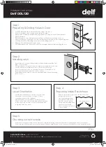
Step 9
Mounting Inside Escutcheon
•
Carefully mount the inside escutcheon, aligning it
with the spindle through the lever hub and also to the
mounting plate holes and posts.
•
NOTE: Be careful to not crush the internal wire
connection when fixing the inside escutcheon –
ensure cables are neatly tucked into cavity area in
the escutcheon.
•
Insert and firmly tighten with a screwdriver the third
mounting screw to the top hole in the back of the
inside escutcheon, and then do the same with the
two black screws on the bottom two holes of the
escutcheon.
•
The mounting of the unit on the door is now complete.
Step 10
Door Striker
Installation
•
Ensure door seals are installed
before installing the strike plate.
•
Gently close the door until the
latch-bolt rests on the door
jamb (picture A)
•
Mark the centre of the bolt on
the door jamb, this mark can be
used to position strike plate.
•
Mark and drill 25mm hole inside
the door jamb to a depth of
14mm on marked bolt centre
position.
•
Position the strike plate and
mark around. Chisel a recess
until the strike plate sits flush
with the door jamb face.
(Picture B)
•
Fasten strike plate to door jamb
with two strike plate screws
(#8 x 25mm) (Picture C)
Step 7
Mounting
Interior Plate
•
Carefully push wire from
outside escutcheon
through hole in inside
mounting plate (A).
•
Hold inside mounting
plate to inside of door
(with gasket against the
door, and the two small
posts facing away from
door, insert two screws
and firmly tighten with
a screwdriver through
mounting holes (B).
Step 6
Mounting Exterior Escutcheon
•
Attach spindle to front escutcheon hub. Align the
holes in the hub with the hole in the end of the spindle,
and secure using the split pin provided.
•
Mount exterior escutcheon onto front of door, aligning
the bottom two posts to go through the latch, and the
top post to go through the top 15mm hole drilled from
the template, and the wire to go through the middle
15mm hole.
•
Be careful not to damage the wire connector as it is
pushed through the hole.
Step 8
Joining wire connector
•
Carefully join the inside escutcheon wire with the
outside wire, making sure they align and click together.
Step 11 Insert Batteries
•
Insert 4 x AA batteries into the unit ensuring to align
polarity of batteries correctly.
•
Programming the lock is now required – see User Manual
for further instructions.
Installation Instructions
Delf DDL120
DELF ARCHITECTURAL
|
ABN 71 621 592 907
T
1300 362 625
| E
sales@delfarchitectural.com.au
|
W
www.delfarchitectural.com.au
PLEASE RECYCLE
THESE INSTRUCTIONS
B
A
A
B
C
Delf DDL120 v04.indd 2
9/07/2020 10:17:28 AM


