background image

6000XL Series Service and Installation Manual

11

For customer service, call (800) 733-8829, (800) 733-8821, Fax (888) 779-2040, www.delfield.com

Delfield

®

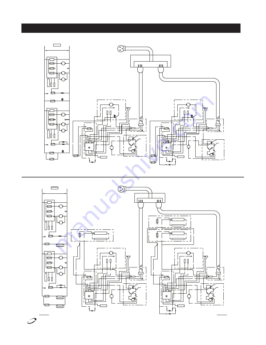
Wiring Diagrams: Refrigerators

6076XL-S, 6076XL-SH

6076XL-G, 6076XL-GH

REVISIONS

LOCATION

DIMENSIONS ARE IN INCHES

TOLERANCES

ALL PARTS TO BE DEBURRED AND EDGES

UNLESS OTHERWISE SPECIFIED

THIRD ANGLE

PROJECTION

The contents of this document are

PROPRIETARY TO THE DELFIELD COMPANY

and are not to be disclosed to others

intended without the written approval

or used for purposes other than

of The Delfield Company.

MATERIAL

PROPRIETARY

BROKEN .010 MAXIMUM.

ANG.   ±

.XXX   ±

.XX    ±

.X     ±

.010

.03

1

.1

C

DO NOT SCALE DRAWING

SCALE

SIGNATURE

PURCH:

MFG:

QA:

L ENNIS

CHECKED:

DRAWN:

05-MAY-2011

DATE

SIZE

DESCRIPTION

1

REV

DESCRIPTION

REV.

COVINGTON, TN

ENODIS

3

SHEET

 OF 

1

1

DWG. NO.

Reach-in Divison

DATE

APPROVED

PLUG

RECEPTICAL BOX

9294477

LED DISPLAY

CONDENSOR FAN

EVAPORATOR FAN

ENERGY SAVER

DOOR

 SWITCHES

 SWITCH

1.1,2,3 2.1,2,3 3.1,2,3

COMPRESSOR

RELAY

CONTROL

TEMPERATURE

LED DISPLA

Y

(IF USED

)

L

EV

AP C

OIL

SENSOR

SENSOR

CABINE

T AIR

1

C

FAN RELAY

CIRCUIT

CONTROL

6

F

5

N

INCANDESCENT

DOOR FRAME

LIGHT

HEATERS

HINGE

 SWITCHES

DOOR

RED 

BLK

DOOR FRAME HEATERS

L

3

TEMPERATURE

CONTROL

1.1,2,3 2.1,2,3 3.1,2,3

BLK

1 2

C L

5

4

H N

6

F

W

W

W

(IF USED)

COMPRESSOR

M

M

M

CONTROL

BOX

P

SWITCH

ENERGY SAVER

GREY

BLUE

CABINE

T AIR

CONDENSER

FAN

BLK

BLK

M

GROUND

MOTOR PROTECTOR

COMPRESSOR

COMPRESSOR

WINDING

WINDINGRUN

14

12

STAR

10

13

11

CAPACITOR

START RELAY

START 

EVAP FAN

WITH BLUE 

STRIPES

W

W

BRN

BLK

W

M

MOTOR

EV

AP C

OIL

SENSOR

SENSOR

Y

W

W

INCANDESCENT

LIGHT

W

EVAPORATOR HOUSING

POWER BOX

SPLICE

WIRE

NUT

LED DISPLAY

HINGE

 SWITCH

DOOR

BLK

FRAME HEATERS

L

3

TEMPERATURE

CONTROL

1.1,2,3 2.1,2,3 3.1,2,3

BLK

1 2

C L

5

4

H N

6

F

W

W

W

(IF USED)

P

CONTROL

BOX

SWITCH

ENERGY SAVER

GREY

BLUE

CABINE

T AIR

12

WINDING

BLK

BLK

CONDENSER

M

FAN

GROUND

MOTOR PROTECTOR

COMPRESSOR

WINDING

COMPRESSOR

STAR

T

RUN

14

13

CAPACITOR

EVAP FAN

BLK

BRN

WITH BLUE 

STRIPES

W

W

W

M

MOTOR

EV

AP C

OIL

SENSOR

SENSOR

Y

W

INCANDESCENT

LIGHT

W

EVAPORATOR HOUSING

START RELAY

POWER BOX

SPLICE

10

11

WIRE

NUT

START 

LINE VOLTAGE

115/60/1

SEE NAMEPLATE FOR MAXIMUM

FUSE SIZE

DOOR

 SWITCH

ENERGY SAVER

 SWITCH

INCANDESCENT

LIGHT

DOOR FRAME

HEATER

HEATER

LED DISPLA

Y

(IF USED

)

EV

AP C

OIL

SENSOR

SENSOR

CABINE

T AIR

1.1,2,3 2.1,2,3 3.1,2,3

RELAY

COMPRESSOR

1

C

CONDENSOR FAN

M

COMPRESSOR

M

FAN RELAY

6

F

CONTROL

CIRCUIT

CONTROL

TEMPERATURE

L

2/3

N
5

M

EVAPORATOR FAN

9294477

L1

N

11"

8

1

2

"

L ENNIS

02-MAY-2011

INITIAL RELEASE

LABEL,WIRING,3DR,REF,

6000XL,ESTAR

RUNNING AND DOORS CLOSED

1) USE COPPER CONDUCTORS ONLY

2) THIS UNIT MUST BE GROUNDED

3) UNIT SHOWN WITH COMPRESSOR 

NOTES:

NOTES:

1. STRIP-TAC ADHESIVE BACKING

2. BLACK PRINT ON WHITE PAPER 

RED 

H

4

RELAY

2/3

RELAY

HEATER

4

H

L ENNIS

17-MAY-2011

2

ADDED L-2/3 DESIGNATION & H-4 FOR HEATER TERMINAL

26-MAY-2011

L ENNIS

BROWN COMPRESSOR WIRE WAS BLACK (ON DIAGRAM ONLY)

3

REVISIONS

LOCATION

DIMENSIONS ARE IN INCHES

TOLERANCES

ALL PARTS TO BE DEBURRED AND EDGES

UNLESS OTHERWISE SPECIFIED

THIRD ANGLE

PROJECTION

The contents of this document are

PROPRIETARY TO THE DELFIELD COMPANY

and are not to be disclosed to others

intended without the written approval

or used for purposes other than

of The Delfield Company.

MATERIAL

PROPRIETARY

BROKEN .010 MAXIMUM.

ANG.   ±

.XXX   ±

.XX    ±

.X     ±

.010

.03

1

.1

C

DO NOT SCALE DRAWING

SCALE

SIGNATURE

PURCH:

MFG:

QA:

L ENNIS

CHECKED:

DRAWN:

05-MAY-2011

DATE

SIZE

DESCRIPTION

1

REV

DESCRIPTION

REV.

COVINGTON, TN

ENODIS

3

SHEET

 OF 

1

1

DWG. NO.

Reach-in Divison

DATE

APPROVED

RECEPTICAL BOX

9294478

11"

8

1

2

"

L ENNIS

02-MAY-2011

INITIAL RELEASE

LABEL,WIRING,3DR,REF,GL DR,

6000XL,ESTAR

CABINE

T AIR

SENSOR

SENSOR

(IF USED

)

LED DISPLA

Y

EV

AP C

OIL

LAMP SWITCH

FLUORESCENT

LAMP 

ENERGY SAVER

FLUORESCENT

 SWITCH

DOOR FRAME

FLUORESCENT

LAMP BALLAST

HEATER

M

RELAY

COMPRESSOR

1.1,2,3 2.1,2,3 3.1,2,3

1

FAN RELAY

HEATER

C

6

COMPRESSOR

CONDENSOR FAN

M

EVAPORATOR FAN

M

9294478

LINE VOLTAGE

115/60/1

SEE NAMEPLATE FOR MAXIMUM

FUSE SIZE

CONTROL

TEMPERATURE

CONTROL

CIRCUIT

L

2/3

N
5

F

L1

N

LAMP 

LAMP 

COMPRESSOR

DOOR FRAME

EVAPORATOR FAN

CONDENSOR FAN

LAMP BALLAST

FLUORESCENT

FLUORESCENT

FLUORESCENT

LAMP BALLAST

FLUORESCENT

SENSOR

SENSOR

EV

AP C

OIL

CABINE

T AIR

LAMP SWITCHES

FLUORESCENT

 SWITCH

ENERGY SAVER

COMPRESSOR

1.1,2,3 2.1,2,3 3.1,2,3

LED DISPLA

Y

(IF USED

)

RELAY

FAN RELAY

C

1

F

6

CONTROL

CIRCUIT

TEMPERATURE

CONTROL

L

5

N

HEATERS

M

M

M

NOTES:

1. STRIP-TAC ADHESIVE BACKING

2. BLACK PRINT ON WHITE PAPER 

1) USE COPPER CONDUCTORS ONLY

2) THIS UNIT MUST BE GROUNDED

NOTES:

3) UNIT SHOWN WITH COMPRESSOR 

PLUG

RUNNING AND DOORS CLOSED

ENERGY SAVER

SWITCH

H

4

1.1,2,3 2.1,2,3 3.1,2,3

CONTROL

TEMPERATURE

BLK

L

C

2

1

3

L

GREY

BOX

CONTROL

P

POWER BOX

COMPRESSOR

(IF USED)

LED DISPLAY

W

BLK

WITH BLUE 

F

6

N

5

W

W

M

W

W

STRIPES

FAN

CONDENSER

BLK

RUN

WINDING

14

12

11

10

13

STAR

T

WINDING

W

BRN

BLK

W

SPLICE

GROUND

MOTOR PROTECTOR

START 

CAPACITOR

COMPRESSOR

START RELAY

NUT

WIRE

EVAPORATOR HOUSING

EVAP FAN

BLUE

SENSOR

SENSOR

EV

AP C

OIL

CABINE

T AIR

Y

M

MOTOR

W

W

BLK

FLUORESCENT LAMP ASSEMBLY

RED

RED

LAMP 

SWITCH

FLUORESCENT

BLK

BLK

W

SWITCH

LAMP 

FLUORESCENT

BLK

FLUORESCENT LAMP 

FLUORESCENT LIGHT

FLUORESCENT LAMP 

BALLAST

BLUE

W

FLUORESCENT LIGHT

BALLAST

BLUE

P

BLK

DOOR FRAME HEATERS

BLK

GREY

1.1,2,3 2.1,2,3 3.1,2,3

ENERGY SAVER

P

CONTROL

BLK

BOX

P

FLUORESCENT

SWITCH

LAMP 

BLK

W

CABINE

T AIR

EV

AP C

OIL

WINDING

STAR

T

14

DOOR FRAME HEATER

BLK

W

TEMPERATURE

5

3

1 2

CONTROL

4

6

LED DISPLAY

(IF USED)

W

BLK

CONDENSER

M

FAN

WINDINGRUN

N

L

C L

H

F

W

SWITCH

W

BLUE

SENSOR

BRN

BLK

W

BLK

10

12

STRIPES

W

WITH BLUE 

SENSOR

W

W

13

MOTOR PROTECTOR

COMPRESSOR

COMPRESSOR

GROUND

START RELAY

CAPACITOR

START 

11

POWER BOX

SPLICE

WIRE

NUT

BLUE

EVAPORATOR HOUSING

FLUORESCENT LAMP ASSEMBLY

Y

FLUORESCENT LIGHT

FLUORESCENT LAMP 

RED

BALLAST

MOTOR

M

EVAP FAN

ADDED HEATER RELAY TO CONTROL & L-2/3 DESIGNATION

2

17-MAY-2011

L ENNIS

RELAY

H

4

RELAY

HEATER

4

H

2/3

L ENNIS

26-MAY-2011

BROWN COMPRESSOR WIRE WAS BLACK (ON DIAGRAM ONLY)

3

Summary of Contents for 6100XL

Page 1: ...read this manual completely before attempting to install or operate this equipment Notify carrier of damage Inspect all components immediately See page 2 Refrigerators and Freezers April 2012 IMPORTANT INFORMATION READ BEFORE USE PLEASE SAVE THESE INSTRUCTIONS Delfield 9294254 ...

Page 2: ...without written permission is prohibited Delfield is a registered trademark of The Delfield Company Contents Serial Number Information Even though most equipment is shipped crated care should be taken during unloading so the equipment is not damaged while being moved into the building 1 Visually inspect the exterior of the package and skid or container Any damage should be noted and reported to th...

Page 3: ...3 2092 2488 20 F 12 5 12 5 774lbs 351kg 5 20p 6125XL S SH 115 9 0 20 0 15 1 1 2 2092 20 F 12 5 274lbs 124kg 5 15p 6151XL S SH 115 12 0 43 5 33 2 3 4 1923 20 F 12 5 454lbs 206kg 5 15p 6176XL S SH 120 208 230 20 0 66 5 48 3 1 2 3 4 1516 1923 20 F 12 5 12 5 622lbs 282kg 14 20P Model Voltage Amps Storage Capacity FT3 Shelf Capacity FT2 Required BTU HR Evap Temp ShippingWeight 6025XLR SH S 115 5 0 20 0...

Page 4: ...port the total weight of the cabinet and contents A fully loaded 6000XL series can weigh as much as 1500 pounds Reinforce the floor as necessary to provide for maximum loading For the most efficient refrigeration be sure to provide good air circulation inside and out Inside cabinet Do not pack refrigerator so full that air cannot circulate The refrigerated air is discharged at the top rear of the ...

Page 5: ...s by pulling straight up then rotating the cam 180 and pushing back into the hinge 9 Remount the door and check for proper closure and gasket seal Adjust hinges as needed Once adjustment is verified remove the door reinstall all hinge screw covers and set the door back in place 10 If plugs are needed to plug old screw holes in cabinet face frame please contact Delfield Parts Department at 800 733 ...

Page 6: ...red panel on the left side It is factory set at mid range to maintain about 38 F 3 C box temperature To adjust for colder temperatures turn the knob clockwise For warmer temperatures turn the knob counter clockwise Turn the knob fully counter clockwise to turn the refrigeration system off Never turn the knob more than 1 dial number and always allow 8 hours for temperature stabilization before maki...

Page 7: ...lecting the condenser coil cleaning procedures will void any warranties associated with the compressor or cost to replace the compressor Freezer Whenever the freezer is plugged in and the control has completed initializing including the initial defrost cycle also see Electronic Temperature Control Operation on this page The digital therostat will display box temperature The temperature control wil...

Page 8: ...ughly and start to apply stainless steel cleaners in attempt to restore the passivity of the steel Never use an acid based cleaning solution Many food products have an acidic content which can deteriorate the finish Be sure to clean the stainless steel surfaces of ALL food products Common items include tomatoes peppers and other vegetables Gasket Maintenance Gaskets require regular cleaning to pre...

Page 9: ...17 MAY 2011 ADDED L 2 3 DESIGNATION H 4 FOR HEATERTERMINAL 2 3 BROWN COMPRESSORWIREWAS BLACK ON DIAGRAM ONLY 26 MAY 2011 L ENNIS DESCRIPTION SIZE C SCALE UNLESS OTHERWISE SPECIFIED X XX XXX ANG BROKEN 010 MAXIMUM ALL PARTSTO BE DEBURRED AND EDGES PROJECTION THIRD ANGLE or used for purposes other than ofThe Delfield Company intended without the written approval MATERIAL and are not to be disclosed ...

Page 10: ...OTECTOR COMPRESSOR COMPRESSOR WINDING W IN D IN G R U N 14 12 STAR 10 13 11 CAPACITOR START RELAY START BLK BLK M CONDENSER FAN MOTOR 02 MAY 2011 NOTES 1 STRIP TAC ADHESIVE BACKING 2 BLACK PRINT ONWHITE PAPER 17 MAY 2011 ADDED HEATER RELAYTO CONTROL L 2 3 DESIGNATION 2 H 4 HEATER RELAY BROWN COMPRESSORWIREWAS BLACK ON DIAGRAM ONLY 3 26 MAY 2011 DESCRIPTION SIZE C SCALE UNLESS OTHERWISE SPECIFIED X...

Page 11: ...IREWAS BLACK ON DIAGRAM ONLY 3 REVISIONS LOCATION DIMENSIONS ARE IN INCHES TOLERANCES ALL PARTSTO BE DEBURRED AND EDGES UNLESS OTHERWISE SPECIFIED THIRD ANGLE PROJECTION The contents of this document are PROPRIETARYTOTHE DELFIELD COMPANY and are not to be disclosed to others intended without the written approval or used for purposes other than ofThe Delfield Company MATERIAL PROPRIETARY BROKEN 010...

Page 12: ...6000XL Series Service and Installation Manual For customer service call 800 733 8829 800 733 8821 Fax 888 779 2040 www delfield com 12 Delfield Wiring Diagrams Freezers 6125XL S 6125XL SH ...

Page 13: ...ING L N L N EVAPORATOR HOUSING LINEVOLTAGE 115 208 230 60 1 SEE NAMEPLATE FOR MAXIMUM FUSE SIZE DEFROST HEATER EVAPORATOR FAN CIRCUIT COMPRESSOR RELAY 1 1 2 32 1 2 33 1 2 3 SENSOR CABINET AIR SENSOR EVAP COIL IF USED LED DISPLAY 5 F 3 6 4 H C FAN RELAY HEATER RELAY 1 N CONTROL L TEMPERATURE CONTROL L1 CIRCUIT COMPRESSOR M COMPRESSOR CONDENSOR FAN M COMPRESSOR CONDENSOR FAN RELAY 1 1 2 32 1 2 33 1 ...

Page 14: ...tallation Manual For customer service call 800 733 8829 800 733 8821 Fax 888 779 2040 www delfield com 14 Delfield Refrigeration Package Diagram 4 3 2 9 6 5 1 11 13 14 15 16 17 18 21 7 5 6 1 9 4 14 11 12 18 15 17 16 3 7 8 21 20 19 ...

Page 15: ...nt 19 2194785 2194967 Heater defrost 20 9321629 Clip defrost heater mounting 21 2194953 Switch defrost safety high limit 1702795 Condensate pan 3516041 Solenoid valve used on remote units Refrigerator 2 section 3 section right package Item Number Part Number 220V 50Hz Part Description 1 3516437 Coil evaporator 2 kit 2194811KT 2194988KT Temperature Control 3 2190154 Switch energy saver 4 2184181 Co...

Page 16: ...ll Door s s hinged right edge mount hinges 000 AB9 013P Half Door s s bottom left edge mount hinges 000 AB9 013R Half Door s s bottom right edge mount hinges 000 AB9 013M Half Door s s top left edge mount hinges 000 AB9 013N Half Door s s top right edge mount hinges 3234617KT Hinge 1 5 16 offset with adjustable housing 1702796 Gasket full door s s 1702797 Gasket half door s s Glass Door Replacemen...

Page 17: ... reimbursed under warranty unless pre approved with a Service Work Authorization from Delfield You must submit the number with the service claim LABOR OF 1 HOUR IS ALLOWED TO REPLACE Thermostat Door Jamb Switch Evaporator Condenser Fan Motor and Blade Solenoid Coil Hi limit Thermal Protector Switch Fan Delay Defrost Termination Switch Compressor Start Components and Overload Protector Door Hinges ...

Page 18: ... paragraph may void warranty coverage Procedures All claims for replacement parts or repair kits must be made through a Delfield Parts Depot or an authorized Delfield dealer The defective part invoice must be returned to Delfield within 15 days after the date of service to be eligible for warranty coverage All claims must include the model number serial number an original date of installation and ...

Page 19: ... APPLICABLE TIME AND MATERIALS RATES CONSIDER CUSTOMER MAY INITIATE A SERVICE AGREEMENT WITHOUT PARTS COVERAGE If shipment of a replacement part is requested prior to the arrival in the Delfield factory of the part claimed to be defective the Original Purchaser must accept delivery of the replacement part of a C O D basis with credit being issued after the part has been received and inspected at D...

Page 20: ..._______ Installation Date _______________ For a list of Delfield s authorized parts depots visit our website at www delfield com Delfield Mt Pleasant MI Covington TN 980 S Isabella Rd Mt Pleasant MI 48858 U S A 989 773 7981 or 800 733 8829 Fax 989 773 3210 www delfield com Delfield reserves the right to make changes in design or specifications without prior notice 2012 The Delfield Company All rig...

Reviews: