background image

Section 2 

Installation

Part Number: 9294839  03/17 

13

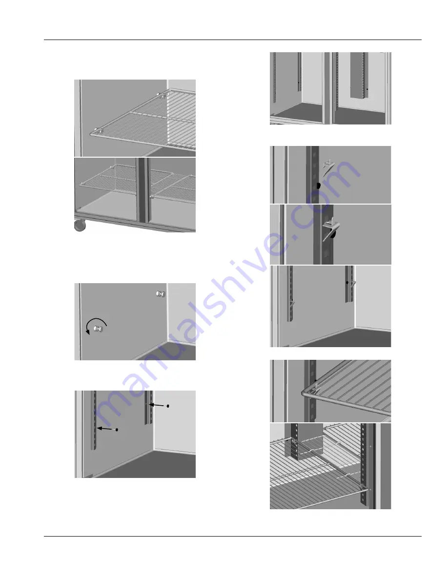
Pilaster Clip Kit Installation Instructions

APPLICABLE TO GC MODELS

1.  If the shelves are attached to the shelf pins, detach and 

set them aside. Cut zip ties if necessary.

2.  Remove the shelf pins from refrigerator side walls 

and mullions. These holes will be used to mount the 

pilasters.

3.  Match up the pilaster mounting holes with the 

refrigerator and mullion holes. Secure with provided 

screws.

4.  Insert the clips into the pilaster holes at the desired 

shelf heights.

5.  Set the shelves on the clips.

Summary of Contents for CoolScapes GB Series

Page 1: ...each Ins CoolScapes Original Instructions Installation Operation and Maintenance Manual This manual is updated as new information and models are released Visit our website for the latest manual Part Number 9294839 03 17 ...

Page 2: ...this product could expose you to airborne particles of glasswool or ceramic fibers crystalline silica and or carbon monoxide Inhalation of airborne particles of glasswool or ceramic fibers is known to the State of California to cause cancer Inhalation of carbon monoxide is known to the State of California to cause birth defects or other reproductive harm nWarning Do not use electrical appliances o...

Page 3: ...ter Models 11 Pilaster Clip Kit Installation Instructions 12 Applicable to GC Models 12 New Bottom Hinge Cartridge Installation 13 T 1 Tray Slide Installation 14 T 2 Tray Slide Installation 15 T 3 Tray Slide Installation 16 T 4 Rack Slide Installation 17 Section 3 Operation R290 Controls Programming Settings 19 R290 Temperature Control Display 20 R290 Evaporator Fan Operation 21 R290 Changing Disp...

Page 4: ...SF1P S H GBSF2P S H GBSF3P S H GCF1P S H GCF2P S H GCF3P S H Serial Number Information The serial number is on the identification plate that also includes the model number The identification plate is located near the top front corner of the left interior wall Always have the serial number of your unit available when calling for parts or service Warranty Information Visit http www delfield com warr...

Page 5: ...o back nWarning This equipment is intended for indoor use only Do not install or operate this equipment in outdoor areas The location selected for the equipment must meet the following criteria If any of these criteria are not met select another location The location MUST be level stable and capable of supporting the weight of the equipment The location MUST be free from and clear of combustible m...

Page 6: ... kg GCR3P S H 668 lbs 303 kg 1 Section Freezers Solid Doors GBF1P S H 336 lbs 152 kg GBSF1P S H 354 lbs 161 kg GCF1P S H 299 lbs 136 kg 2 Section Freezers Solid Doors GBF2P S H 532 lbs 241 kg GBSF2P S H 495 lbs 225 kg GCF2P S H 445 lbs 202 kg 3 Section Freezers Solid Doors GBF3P S H GBSF3P S H 772 lbs 350 kg GCF3P S H 707 lbs 321 kg Clearance Requirements DANGER Minimum clearance requirements are ...

Page 7: ...S H 27 34 70cm 32 44 82cm 79 50 202cm 2 Section Freezers GBF2P S H GBSF2P S H GCF2P S H 55 16 140cm 32 44 82cm 79 50 202cm 3 Section Freezers GBF3P S H GBSF3P S H GCF3P S H 82 97 211cm 32 44 82cm 79 50 202cm Model Volume 1 Section Refrigerators GBR1P G H GBR1P S H GBSR1P G H GBSR1P S H GCR1P G H GCR1P S H 21ft3 595L 2 Section Refrigerators GBR2P G H GBR2P S H GBSR2P G H GBSR2P S H GCR2P G H GCR2P ...

Page 8: ...protection is a system that shuts down the electric circuit opens it when it senses an unexpected loss of power presumably to ground Manitowoc does not recommend the use of GFCI GFI circuit protection to energize our equipment If code requires the use of a GFCI GFI then you must follow the local code The circuit must be dedicated sized properly and there must be a panel GFCI GFI breaker We do not ...

Page 9: ...3g Half Height Doors GBR2P GH GBSR2P GH GCR2P GH 2540 880 113g Solid Full Height Doors GBR2P S GBSR2P S GCR2P S 2540 565 113g Half Height Doors GBR2P SH GBSR2P SH GCR2P SH 2540 590 113g 3 Section Refrigerators Glass Full Height Doors GBR3P G GBSR3P G GCR3P G 3865 1175 118g Model BTU Hour Capacity Heat of Rejection BTU Charge Solid Full Height Doors GBR3P S GBSR3P S GCR3P S 3865 850 118g Half Heigh...

Page 10: ... with all applicable codes nWarning The unit must be installed in a stable condition with the front wheels locked Locking the front casters after installation is the owner s and operator s responsibility nWarning Use a jack to lift the refrigeration unit off the ground just far enough to remove the leg caster Place blocking underneath the unit Do not work underneath a raised unit without proper bl...

Page 11: ... them aside Cut zip ties if necessary 2 Tighten the shelf pins to the refrigerator side walls and mullions Caution Shelf pins can be become damaged and unusable if shelves are loaded while the pins are loose 3 Place the shelves back on the pins APPLICABLE TO GB MODELS 1 Insert the clips into the pilaster holes at the desired shelf heights 2 Set the shelves on the clips ...

Page 12: ...move three bolts securing the hinge bracket to the bottom of the unit 7 Flip it over and install it on the opposite side 8 Rotate the door 180 9 Move the white nylon washer from the top hinge pin to the bottom hinge pin 10 Insert the bottom hinge pin into the hinge bracket 11 Locate the provided alternate top hinge bracket 12 Place the hinge bracket over the top hinge pin 13 Open the door 14 Using...

Page 13: ...ach and set them aside Cut zip ties if necessary 2 Remove the shelf pins from refrigerator side walls and mullions These holes will be used to mount the pilasters 3 Match up the pilaster mounting holes with the refrigerator and mullion holes Secure with provided screws 4 Insert the clips into the pilaster holes at the desired shelf heights 5 Set the shelves on the clips ...

Page 14: ...rotate it turn to the outside of the door 3 After the hinge has been rotated it will now be in the OPEN position and NOT under spring tension 4 Mount the door back onto the cabinet with the door OPEN The door should now close properly 5 Begin closing the door the door should finish closing on it s own If the door stays open remove the door and hinge bracket 6 Using the hinge bracket rotate the squ...

Page 15: ...mounted every 3 and the top and bottom of each tray slide is used to hold a pan Centers 1 5 2 0 3 0 4 0 5 0 6 0 Maximum Tray Slides for a Full Section 17 26 17 13 10 8 Maximum Tray Slides for a Half Section Top 7 10 6 5 4 4 Maximum Tray Slides for a Half Section Bottom 8 12 8 6 5 4 T 1 Installation Instructions 1 For each pan mount a pair of tray slides one on each side of the door section at the ...

Page 16: ...enters 2 0 3 0 4 0 5 0 6 0 Maximum Tray Slides for a Full Section 25 17 12 10 8 Maximum Tray Slides for a Half Section Top 10 6 5 4 4 Maximum Tray Slides for a Half Section Bottom 10 6 6 5 4 T 2 Tray Slide System T 2 Installation Instructions 1 For each pan two 2 tray slides will be used Each tray slide must have another tray slide at the same height on the opposite side of the door section Mount ...

Page 17: ...Slides for a Full Section 17 12 9 7 Maximum Tray Slides for a Half Section Top 6 5 4 3 Maximum Tray Slides for a Half Section Bottom 8 6 5 4 T 3 Installation Instructions 1 For each pan two 2 tray slides will be used Each tray slide must have another tray slide at the same height on the opposite side of the door section Mount the tray slides onto the pilasters by sliding the tabs down into the pil...

Page 18: ...ssembling the mounting plates at the bottom of the door section Place a bottom mounting plate so that each set of tabs engages a cutout on the pilaster Push the mounting plate down to secure the plate to the cutouts NOTE A dead blow hammer is recommended to seat the tab into the cutouts 2 On the same side place a top mounting plate with the bottom edge 20 51cm above the top of the lower mounting p...

Page 19: ...or to the blower coil R290 Controls Programming Settings R290 Refrigerator Refrigerators are factory set at mid range to maintain about 38ºF 3ºC box temperature 1 At initial start up or anytime power is disconnected then reconnected to the unit the control will go into defrost mode 2 The control will enter a DEFROST mode and the display will read dEF The compressor and condenser fan as well as the...

Page 20: ...onds or unplug the unit for several seconds then plug unit back in This will cause the control to re initialize and then enter a defrost cycle When the control enters the defrost mode it switches off the evaporator fan motor compressor and condenser fan motor and switches on the defrost heater to warm the evaporator coil Thereby melting all frost accumulated during the previous refrigeration cycle...

Page 21: ...electrical box behind the front shroud It controls the length of time that heat is applied to the door perimeter The normal operating position for this switch is the on position providing the shortest amount of time If excessive condensation is observed on the door opening switch to the off position with the help of an authorized service agent The off position will increase the length of time the ...

Page 22: ... push the stand by button lower left button to enter into the display menu 5 Scroll to CFu using the up down arrows and push the stand by button lower left button to enter the display unit menu 6 F should be displayed indicating Fahrenheit Use the down arrow to change it to C for Celsius and hit the stand by button lower left button to enter the change 7 Push the defrost button upper left button t...

Page 23: ...ratic operation nWarning Never use sharp objects or tools to remove ice or frost Do not use mechanical devices or other means to accelerate the defrosting process Cleaning and Sanitizing Procedures Caution Maintenance and servicing work other than cleaning as described in this manual must be done by an authorized service personnel GENERAL nWarning When using cleaning fluids or chemicals rubber glo...

Page 24: ...s of ALL food products Clean the area around the unit as often as necessary to maintain cleanliness and efficient operation Wipe gasket and surfaces with a damp cloth rinsed in water to remove dust and dirt from the outside of the unit Always rub with the grain of the stainless steel to avoid marring the finish If a greasy residue persists use a damp cloth rinsed in a mild dish soap and water solu...

Page 25: ...cleaning should be increased Clean the condenser with a vacuum cleaner or stiff brush If extremely dirty a commercially available condenser cleaner may be required Failure to maintain a clean condenser coil can initially cause high temperatures and excessive run times Continuous operation with a dirty or clogged condenser coil can result in compressor failure Neglecting the condenser coil cleaning...

Page 26: ...26 Part Number 9294839 03 17 Maintenance Section 4 THIS PAGE INTENTIONALLY LEFT BLANK ...

Page 27: ...low adequate time for product to cool down Prolonged door openings or door s ajar Make sure door s are closed when not in use Avoid prolonged door openings Dirty condenser coil Clean the condenser coil Evaporator coil iced over Turn unit off and allow coil to defrost Make sure thermostat is not set too cold Also check gasket condition Cabinet is noisy Loose part s Locate and tighten loose part s R...

Page 28: ...at www welbilt com then discover the regional or local resources available to you Every new piece of Welbilt equipment comes with KitchenCare and you choose the level of service that meets your operational needs from one restaurant to multiple locations StarCare Warranty lifetime service certified OEM parts global parts inventory performance audited ExtraCare CareCode 24 7 Support online mobile pr...

Reviews: