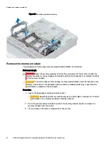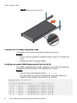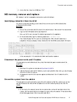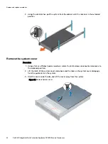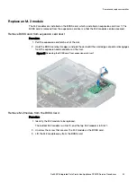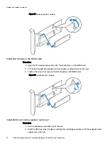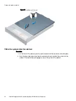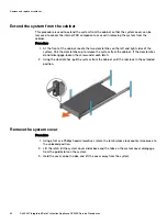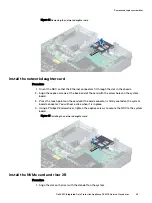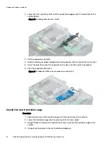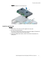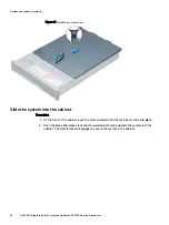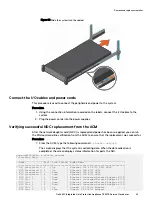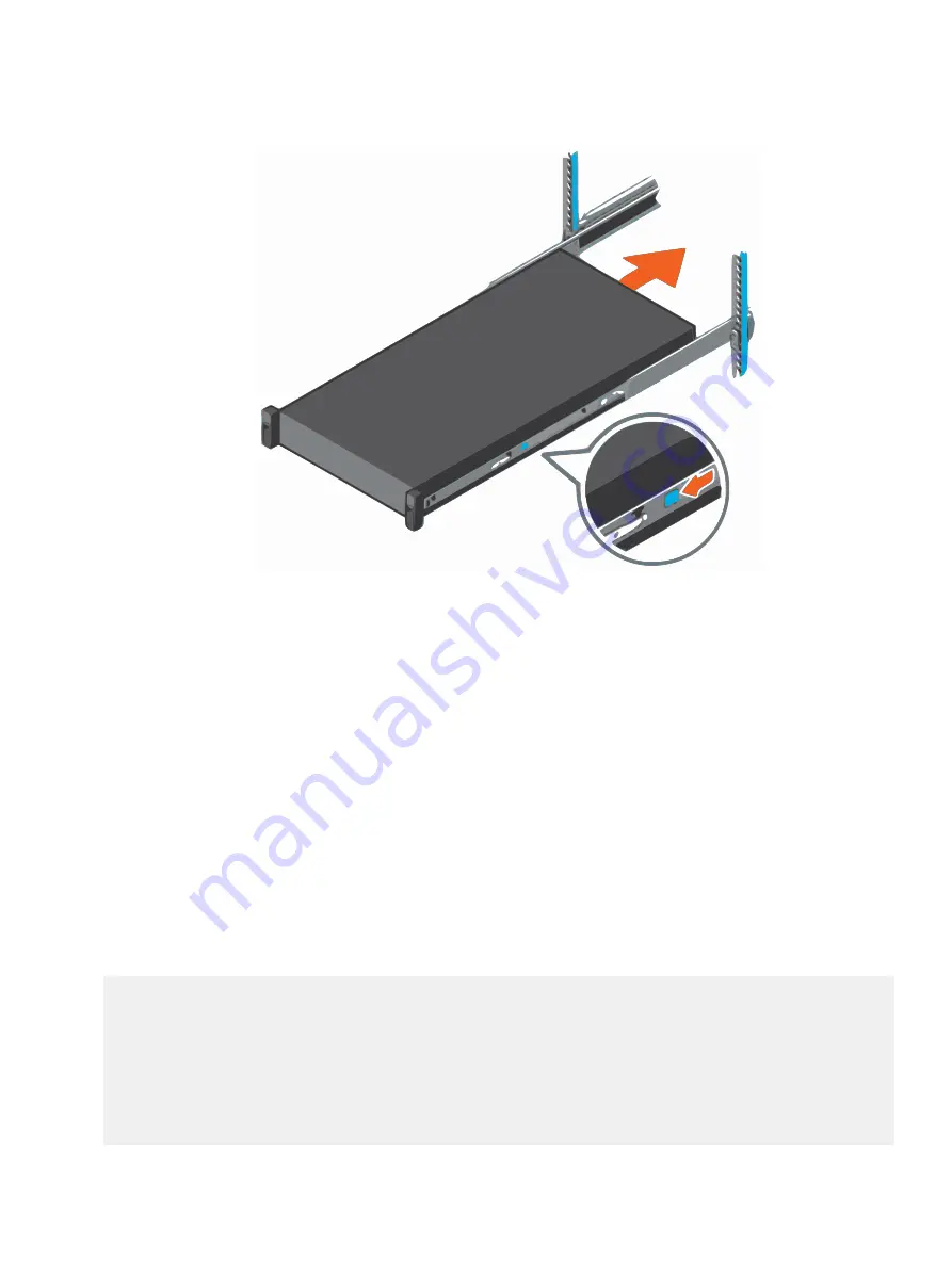
Figure 38 Slide the system into the cabinet
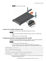
Connect the I/O cables and power cords
This procedure is used to connect the peripherals and power to the system.
Procedure
1. Using the connection information recorded on the labels, connect the I/O cables to the
system.
2. Plug the power cords into the power supplies.
Verifying successful M.2 card replacement from the ACM
After an M.2 card is replaced and power has been re-applied, you can run the FRU command line
verification from the ACM to ensure that the replacement was successful.
Procedure
1. From the ACM, type the following command:
# showfru boss
The screen displays that the system is collecting data. When the data collection is
completed, the screen displays status information for the BOSS card and both M.2 cards.
acme-dp4400-ACM:~ # showfru boss
Collecting Data............
_____________________________________
| ID | State| Status| FW Version |
|====================================|
| BOSS-S1| 0 | OK | 2.5.13.2008|
________________________________________________________________
| ID | State | Status| FW Version| Capacity| Operation| OpStatus|
|===============================================================|
| 0-0| Online| OK | N201DL43 | 111.79GB| None | 0% |
| 1-1| Online| OK | N201DL43 | 111.79GB| None | 0% | *
2. Verify that the status for the BOSS card is "OK". Verify that the state for both M.2 cards is
"Online" and the statuses are "OK".
Remove and replace assemblies
Dell EMC Integrated Data Protection Appliance DP4400 Service Procedures
53

