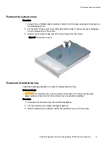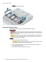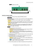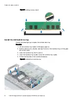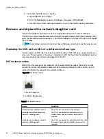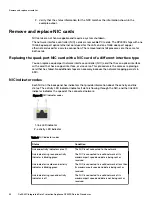
Table 7 NIC indicator codes (continued)
Status
Condition
Link indicator is green and activity
indicator is off
The NIC is connected to a valid network at its
maximum port speed and data is not being sent or
received.
Link indicator is amber and activity
indicator is off
The NIC is connected to a valid network at less than
its maximum port speed and data is not being sent
or received.
Link indicator is blinking green and
activity is off
NIC identify is enabled through the NIC
configuration utility.
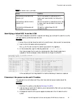
Identifying a failed NDC from the ACM
If the network daughter card (NDC) is suspected of failing, you can check the web UI or use the
FRU command line verification from the ACM.
Procedure
1. Access the web UI and check for alerts in the Health screen. Click an alert for more details.
2. Log in to the ACM command line by using SSH.
Use
root
for the user, and use the common password for the appliance.
3. At the command line, type the following command:
# showfru network
The screen displays that the system is collecting data. When the data collection is
completed, the screen displays status information for the ports on the NIC.
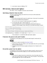
acme-dp4400-ACM:~ # showfru network
Collecting Data............
______________________________________________________________________________
| Name | Port| Link Status| Model Name |
|=============================================================================|
| NIC Integrated 1| 1 | Up | Ethernet 10G 4P X710 SFP+ rNDC |
| NIC Integrated 1| 2 | Error | Ethernet 10G X710 rNDC |
| NIC Integrated 1| 3 | Down | Ethernet 10G X710 rNDC |
| NIC Integrated 1| 4 | Down | Ethernet 10G X710 rNDC |
| NIC Slot 1 | 1 | Down | Ethernet Converged Network Adapter X710|
| NIC Slot 1 | 2 | Down | Ethernet Converged Network Adapter X710|
| NIC Slot 1 | 3 | Down | Ethernet Converged Network Adapter X710|
| NIC Slot 1 | 4 | Down | Ethernet Converged Network Adapter X710|
| NIC Slot 2 | 1 | Up | Gigabit 2P I350-t Adapter |
In this example, port 2 of Integrated NIC 1 is faulted, indicating it needs to be replaced.
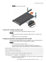
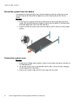
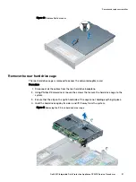
Disconnect the power cords and I/O cables
This procedure is used to disconnect the system from electrical power and disconnect the
peripherals.
Procedure
1. Shut down the system as described in
.
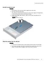
2. Label each power cord and I/O cable so you can easily identify them when you need to plug
them in to restore the system.
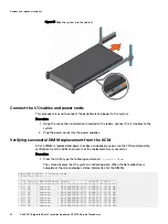
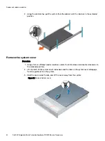
3. Unplug power cords from the power supplies and disconnect the I/O cables from the
system.
Remove and replace assemblies
Dell EMC Integrated Data Protection Appliance DP4400 Service Procedures
55

