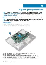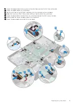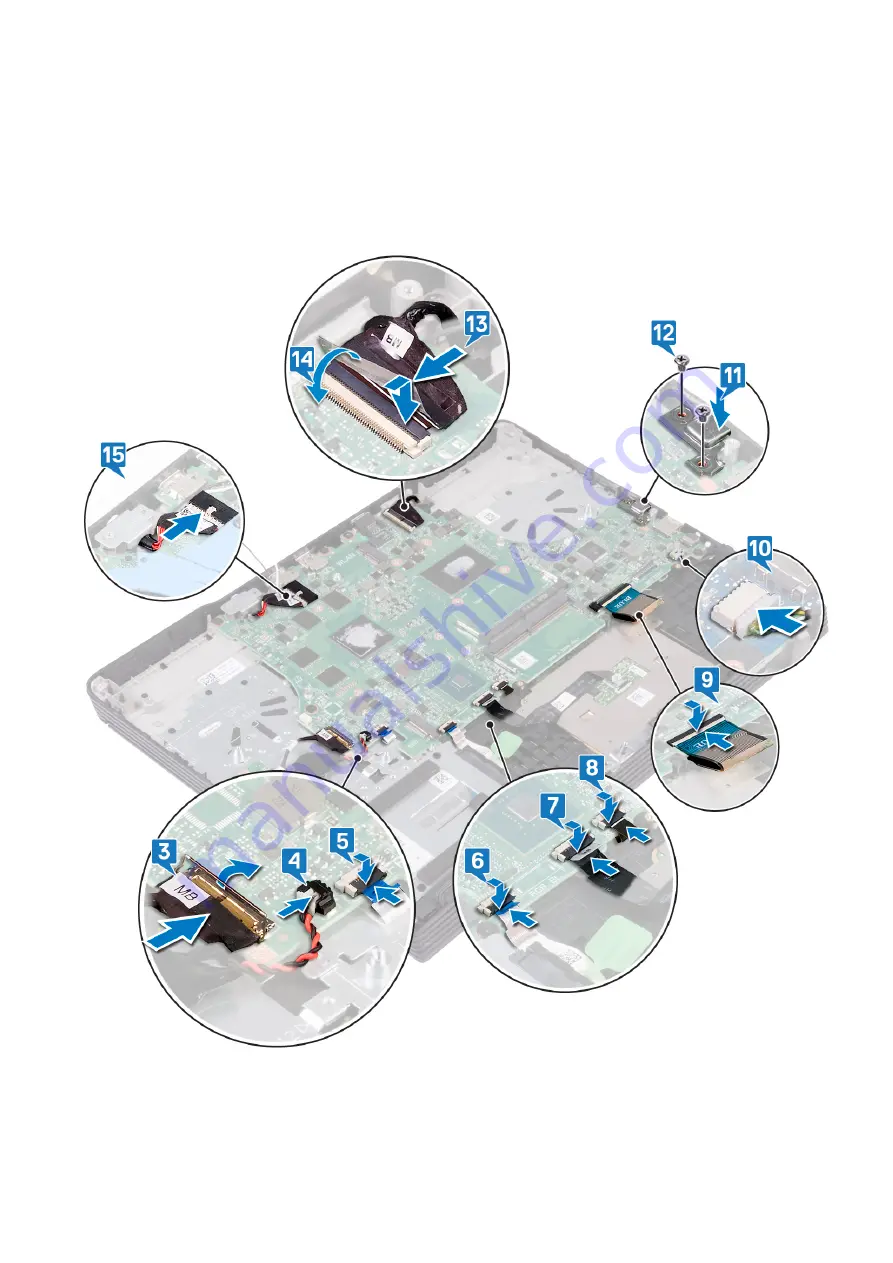
9. Connect the keyboard cable to the connector on the system board and close the latch to secure the cable.
10. Connect the speaker cable to the system board.
11. Align the screw holes on the USB Type-C port bracket with the screw holes on the system board.
12. Replace the two screws (M2x4) that secure the USB Type-C port bracket to the system board.
13. Connect the display cable to the connector on the system board and close the latch to secure the cable.
14. Adhere the tape that secures the display cable to the system board.
15. Connect the power-adapter port cable to the system board.
Replacing the system board
79
Summary of Contents for G7 7590
Page 1: ...Dell G7 7590 Service Manual Regulatory Model P82F Regulatory Type P82F001 ...
Page 21: ...Replacing the base cover 21 ...
Page 24: ...24 Removing the battery ...
Page 26: ...Post requisites Replace the base cover 26 Replacing the battery ...
Page 28: ...28 Removing the memory modules ...
Page 30: ...Post requisites Replace the base cover 30 Replacing the memory modules ...
Page 33: ...Removing the hard drive 33 ...
Page 37: ...Removing the coin cell battery 37 ...
Page 42: ...42 Removing the touchpad ...
Page 44: ...Post requisites 1 Replace the battery 2 Replace the base cover 44 Replacing the touchpad ...
Page 46: ...46 Removing the solid state drive Intel Optane ...
Page 51: ...Post requisites Replace the base cover Replacing the solid state drive Intel Optane 51 ...
Page 53: ...Removing the wireless card 53 ...
Page 55: ...Post requisites Replace the base cover Replacing the wireless card 55 ...
Page 61: ...Removing the heat sink 61 ...
Page 77: ...Removing the system board 77 ...
Page 82: ...82 Removing the power button with fingerprint reader ...
Page 86: ...4 Lift the keyboard along with its cable off the palm rest assembly 86 Removing the keyboard ...
Page 90: ...90 Removing the palm rest ...

