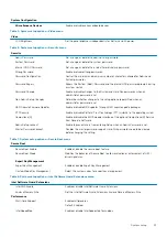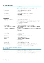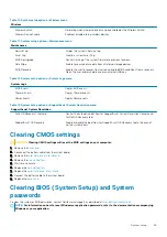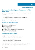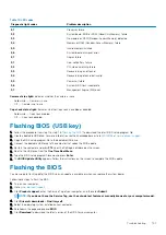
Table 14. LED codes
Diagnostic light codes
Problem description
2,1
Processor failure
2,2
System board: BIOS or ROM (Read-Only Memory) failure
2,3
No memory or RAM (Random-Access Memory) detected
2,4
Memory or RAM (Random-Access Memory) failure
2,5
Invalid memory installed
2,6
System-board or chipset error
2,7
Display failure
3,1
Coin-cell battery failure
3,2
PCI, video card/chip failure
3,3
Recovery image not found
3,4
Recovery image found but invalid
3,5
Power-rail failure
3,6
System BIOS Flash incomplete
3,7
Management Engine (ME) error
Camera status light:
Indicates whether the camera is in use.
•
Solid white — Camera is in use.
•
Off — Camera is not in use.
Caps Lock status light:
Indicates whether Caps Lock is enabled or disabled.
•
Solid white — Caps Lock enabled.
•
Off — Caps Lock disabled.
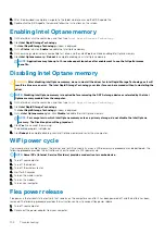
Flashing BIOS (USB key)
1. Follow the procedure from step 1 to step 7 in "
" to download the latest BIOS setup program file.
2. Create a bootable USB drive. For more information see the knowledge base article
3. Copy the BIOS setup program file to the bootable USB drive.
4. Connect the bootable USB drive to the computer that needs the BIOS update.
5. Restart the computer and press
F12
when the Dell logo is displayed on the screen.
6. Boot to the USB drive from the
One Time Boot Menu
.
7. Type the BIOS setup program filename and press
Enter
.
8. The
BIOS Update Utility
appears. Follow the instructions on the screen to complete the BIOS update.
Flashing the BIOS
You may need to flash (update) the BIOS when an update is available or when you replace the system board.
Follow these steps to flash the BIOS:
1. Turn on your computer.
2. Go to
.
3. Click
Product support
, enter the Service Tag of your computer, and then click
Submit
.
NOTE:
If you do not have the Service Tag, use the auto-detect feature or manually browse for your computer model.
4. Click
Drivers & downloads
>
Find it myself
.
5. Select the operating system installed on your computer.
6. Scroll down the page and expand
BIOS
.
7. Click
Download
to download the latest version of the BIOS for your computer.
Troubleshooting
101
Summary of Contents for G7 7590
Page 1: ...Dell G7 7590 Service Manual Regulatory Model P82F Regulatory Type P82F001 ...
Page 21: ...Replacing the base cover 21 ...
Page 24: ...24 Removing the battery ...
Page 26: ...Post requisites Replace the base cover 26 Replacing the battery ...
Page 28: ...28 Removing the memory modules ...
Page 30: ...Post requisites Replace the base cover 30 Replacing the memory modules ...
Page 33: ...Removing the hard drive 33 ...
Page 37: ...Removing the coin cell battery 37 ...
Page 42: ...42 Removing the touchpad ...
Page 44: ...Post requisites 1 Replace the battery 2 Replace the base cover 44 Replacing the touchpad ...
Page 46: ...46 Removing the solid state drive Intel Optane ...
Page 51: ...Post requisites Replace the base cover Replacing the solid state drive Intel Optane 51 ...
Page 53: ...Removing the wireless card 53 ...
Page 55: ...Post requisites Replace the base cover Replacing the wireless card 55 ...
Page 61: ...Removing the heat sink 61 ...
Page 77: ...Removing the system board 77 ...
Page 82: ...82 Removing the power button with fingerprint reader ...
Page 86: ...4 Lift the keyboard along with its cable off the palm rest assembly 86 Removing the keyboard ...
Page 90: ...90 Removing the palm rest ...


