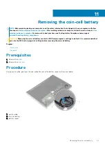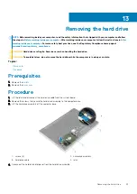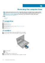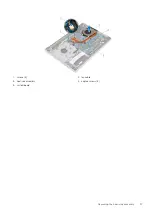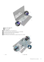
a. screws (13)
b. computer base
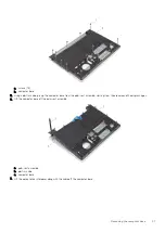
5. Using a plastic scribe, pry up the computer base from the palm-rest assembly, starting from the area around the display hinges.
6. Lift the computer base off the palm-rest assembly.
a. palm-rest assembly
b. plastic scribe
c. computer base
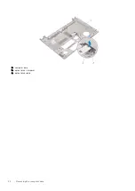
7. Lift the optical-drive interposer along with the cable off the computer base.
Removing the computer base
31
Summary of Contents for Inspiron 14 5000
Page 1: ...Inspiron 14 5000 Service Manual Regulatory Model P64G Regulatory Type P64G002 ...
Page 40: ...3 latch 4 screw 40 Removing the I O board ...
Page 58: ...1 palm rest assembly 58 Removing the palm rest assembly ...
Page 64: ...1 plastic scribe 2 camera cable 3 camera 4 display back cover 64 Removing the camera ...
Page 70: ...a screws 12 b display hinges 2 c display back cover 70 Removing the display hinges ...
Page 73: ...1 display cable 2 display back cover 3 camera cable 4 tape Removing the display cable 73 ...

