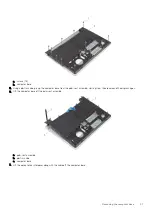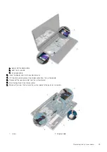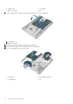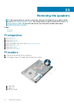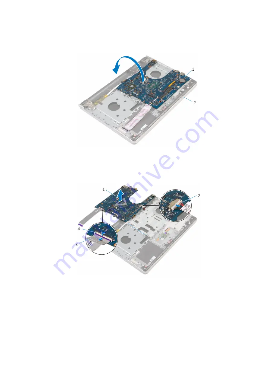
3. speaker cable
4. system board
5. palm-rest assembly
6. tape
8. Lift the system board off the palm-rest assembly and carefully turn the system board over.
a. system board
b. palm-rest assembly
9. Disconnect the power-adapter port cable from the system board.
10. Lift the latch and disconnect the I/O-board cable from the system board.
11. Lift the system board off the palm-rest assembly.
1. system board
2. power-adapter port cable
3. I/O-board cable
4. latch
44
Removing the system board
Summary of Contents for Inspiron 14 5000
Page 1: ...Inspiron 14 5000 Service Manual Regulatory Model P64G Regulatory Type P64G002 ...
Page 40: ...3 latch 4 screw 40 Removing the I O board ...
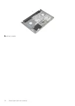
Page 58: ...1 palm rest assembly 58 Removing the palm rest assembly ...
Page 64: ...1 plastic scribe 2 camera cable 3 camera 4 display back cover 64 Removing the camera ...
Page 70: ...a screws 12 b display hinges 2 c display back cover 70 Removing the display hinges ...
Page 73: ...1 display cable 2 display back cover 3 camera cable 4 tape Removing the display cable 73 ...

