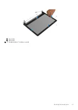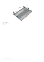
c. antenna cables (2)
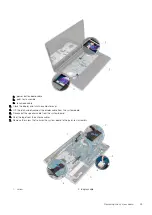
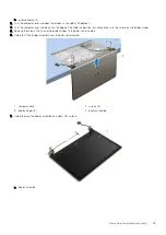
3. Turn the computer over and open the display at an angle of 90 degrees.
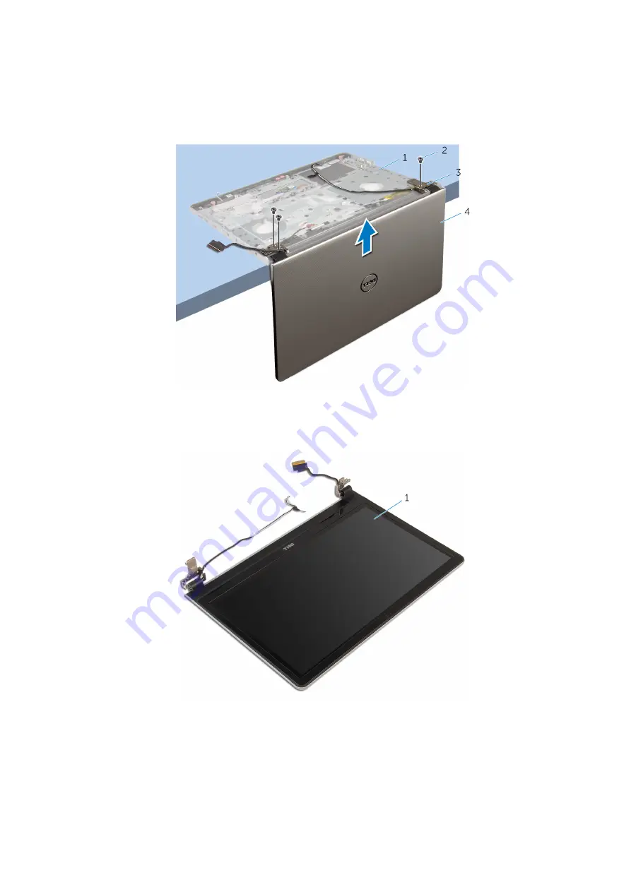
4. Turn the computer over and place it on the edge of the table in a position that allows access to the screws on the display hinges.
5. Remove the screws that secure the display hinges to the palm-rest assembly.
6. Carefully lift the display assembly from the palm-rest assembly.
1. computer base
2. screws (3)
3. display hinges (2)
4. display assembly
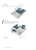
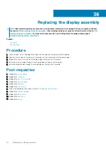
7. Carefully place the display assembly on a clean, flat surface.
a. display assembly
Removing the display assembly
55
Summary of Contents for Inspiron 14 5000
Page 1: ...Inspiron 14 5000 Service Manual Regulatory Model P64G Regulatory Type P64G002 ...
Page 40: ...3 latch 4 screw 40 Removing the I O board ...
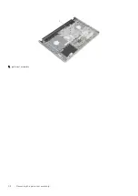
Page 58: ...1 palm rest assembly 58 Removing the palm rest assembly ...
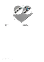
Page 64: ...1 plastic scribe 2 camera cable 3 camera 4 display back cover 64 Removing the camera ...
Page 70: ...a screws 12 b display hinges 2 c display back cover 70 Removing the display hinges ...
Page 73: ...1 display cable 2 display back cover 3 camera cable 4 tape Removing the display cable 73 ...

