Network configuration options
There are two different approaches to configuring the network switches used in this deployment guide. The first approach is the manually
configured approach where a startup-configuration is built up by manually configuring the ports, VLANs, aggregations (physical and
virtual), assigning tagging rules, QoS, and other settings typical to this type of deployment.
The other approach is to use Dell EMC SmartFabric which uses a simplified, reusable approach to configure the switches on the
PowerEdge MX7000 chassis and assign those configurations to the compute resources in the chassis.
The advantage of using the manual configuration method is that every aspect of the switch configuration is available. The switch startup-
configuration reflects every change that is made by the network administrator but this method is slower to deploy and more prone to
human error.
The advantage of SmartFabric is in the time it takes to deploy a configuration. With a relatively small number of configuration steps, a fabric
and profile that can be assigned to the compute sleds are created. When a change is made to the fabric or profile, it can be easily pushed
out to the switches and compute sleds in the PowerEdge MX7000 chassis. The
startup-config
and
running-config
commands
do not reflect the actual configuration of the chassis switches.
Review the sections in both
SmartFabric network configuration
before choosing a path.
Network connectivity
When deploying Dell EMC Networking MX5108n switch modules, the switches are installed in Fabric A of the PowerEdge MX7000
enclosure. Each modular switch has eight internal ports with one port being connected to each compute sled. Two modules provide a
redundant (A1 and A2) connection to each of the PowerEdge MX740c compute sleds. The connection between the compute sleds and the
MX modular switches do not use any kind of link aggregation protocol. The connections are separate network connections that are
managed by the Cloud Foundation stack.
Deploying Dell EMC Networking MX9116n Fabric Switching Engines and Dell EMC Networking MX7116n Fabric Expansion Modules is a
different process. The FSEs are installed into the A1 fabric of the first chassis and the A2 fabric of the second chassis. The FEMs are
distributed across both PowerEdge MX7000 chassis in the remaining A fabric slots. The FEMs connect back to the FSEs using a double
data rate, 200 Gbps cable. The connection between the compute sleds and the MX modular switches do not use any kind of link
aggregation protocol. Additional PowerEdge MX7000 chassis (up to 8 more) can be added and requires only the MX7116n FEMs in the A1
and A2 fabric slots.
The connections from the modular switches to the external network are implemented using Virtual Link Trunking (VLT) link aggregation.
VLT allows you to create a single LACP-managed link aggregation from the two modular switches to an LACP-managed aggregation in the
external network. Use the link aggregation only on the link between the modular switches and the customer network.
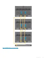
When deploying a single PowerEdge MX7000 chassis using the MX5108n IOMs, the network connectivity is as shown in the following
figure.
Networking requirements
39
Summary of Contents for PowerEdge MX7000
Page 1: ...Dell EMC VMware Cloud Foundation for PowerEdge MX7000 Deployment Guide ...
Page 8: ...Figure 1 Cloud Foundation deployment workflow 8 Overview ...
Page 27: ...Figure 19 Dual PowerEdge MX7000 enclosure configuration Physical layout 27 ...
Page 29: ...Figure 20 MX9002m Management module cabling Physical layout 29 ...
Page 30: ...Figure 21 Connectivity between FSE modules and FEM modules 30 Physical layout ...
Page 31: ...Figure 22 Uplinks to customer network environment Physical layout 31 ...
Page 42: ...Figure 25 MX9002m Management Module cabling 42 Networking requirements ...
Page 43: ...Figure 26 Connectivity between FSE modules and FEM modules Networking requirements 43 ...
Page 44: ...Figure 27 Uplinks to customer network environment 44 Networking requirements ...


