Pre-deployment requirements
Management host
The deployment of VMware Cloud Foundation is executed by a Cloud Builder VM that is deployed using an Open Virtualization Appliance
(OVA). The virtual machine must be deployed on an ESXi host or cluster that is not a part of the Cloud Foundation cluster. If the
management network is a private network (as it is in this example), then deploy an NTP server and a DHCP server on a management host.
In this example, a host in an existing vSphere environment is used to run the services that are required to install Cloud Foundation. The
management VLAN and VXLAN VLAN are extended to this management host. An NTP time server is installed on the management VLAN
and a DHCP server on the VXLAN VLAN.
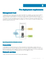
Figure 2. Management host in an existing vSphere environment
Connectivity
The Cloud Builder VM must be able to communicate with the hosts that become the Cloud Foundation management cluster. In this
example, the new cluster hosts were given IP addresses on the 172.16.11.0/24 subnet and placed on the management VLAN (1611). A port
group on the management host that was tagged with VLAN 1611 was created and connected to a port on a switch that accepted (ingress)
traffic. The switchports between that initial ingress port and the new hosts were tagged with VLAN 1611.
Network services
There are three network services that are essential for Cloud Foundation deployment.
3
Pre-deployment requirements
9
Summary of Contents for PowerEdge MX7000
Page 1: ...Dell EMC VMware Cloud Foundation for PowerEdge MX7000 Deployment Guide ...
Page 8: ...Figure 1 Cloud Foundation deployment workflow 8 Overview ...
Page 27: ...Figure 19 Dual PowerEdge MX7000 enclosure configuration Physical layout 27 ...
Page 29: ...Figure 20 MX9002m Management module cabling Physical layout 29 ...
Page 30: ...Figure 21 Connectivity between FSE modules and FEM modules 30 Physical layout ...
Page 31: ...Figure 22 Uplinks to customer network environment Physical layout 31 ...
Page 42: ...Figure 25 MX9002m Management Module cabling 42 Networking requirements ...
Page 43: ...Figure 26 Connectivity between FSE modules and FEM modules Networking requirements 43 ...
Page 44: ...Figure 27 Uplinks to customer network environment 44 Networking requirements ...


