Physical layout
There are multiple configurations of Cloud Foundation on PowerEdge MX7000 chassis that are described in this document. The Cloud
Foundation software addresses the host servers using their IP Address. Deploying compute sleds across multiple PowerEdge MX7000
chassis has no impact on the software as long as the networking is configured properly on the Networking IO modules and the switches to
which the PowerEdge MX7000 chassis connects. The physical layout and resulting cabling is impacted by the number of PowerEdge
MX7000 chassis in use but no other changes are made in the environment.
Topics:
•
•
Configuration options
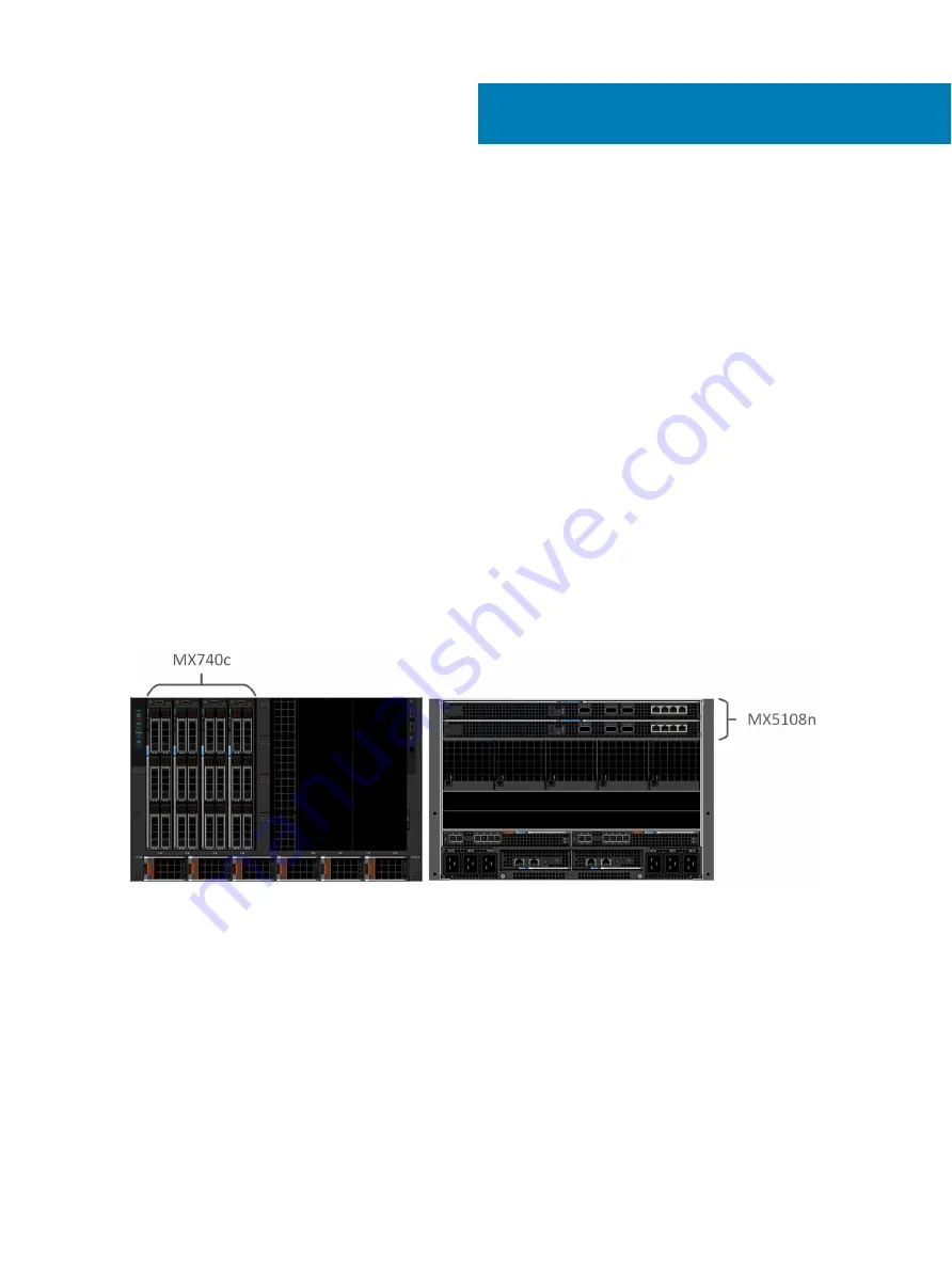
Option 1—single PowerEdge MX7000 enclosure
•
One Dell EMC PowerEdge MX7000 enclosure
•
Four Dell EMC PowerEdge MX740c compute sleds
•
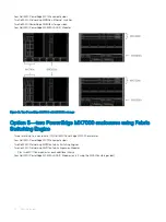
Two Dell EMC Networking MX5108n Ethernet switches
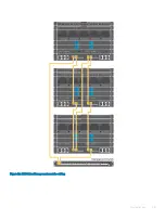
Figure 13. Single PowerEdge MX7000 enclosure
Option 2—single PowerEdge MX7000 with MX5016s storage
sled
•
One Dell EMC PowerEdge MX7000 enclosure
•
Four Dell EMC PowerEdge MX740c compute sleds
•
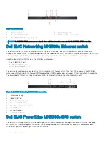
Two Dell EMC Networking MX5108n Ethernet switches
•
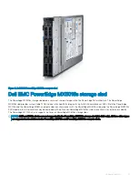
Two Dell EMC PowerEdge MX5016s storage sleds
•
Two Dell EMC PowerEdge MX5000s SAS IO Modules
6
22
Physical layout
Summary of Contents for PowerEdge MX7000
Page 1: ...Dell EMC VMware Cloud Foundation for PowerEdge MX7000 Deployment Guide ...
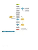
Page 8: ...Figure 1 Cloud Foundation deployment workflow 8 Overview ...
Page 27: ...Figure 19 Dual PowerEdge MX7000 enclosure configuration Physical layout 27 ...
Page 29: ...Figure 20 MX9002m Management module cabling Physical layout 29 ...
Page 30: ...Figure 21 Connectivity between FSE modules and FEM modules 30 Physical layout ...
Page 31: ...Figure 22 Uplinks to customer network environment Physical layout 31 ...
Page 42: ...Figure 25 MX9002m Management Module cabling 42 Networking requirements ...
Page 43: ...Figure 26 Connectivity between FSE modules and FEM modules Networking requirements 43 ...
Page 44: ...Figure 27 Uplinks to customer network environment 44 Networking requirements ...

